U-PROX IC E
Access control panels for building floors


Remote control

Floor Access Control

Over-floor access
Control of access to the floors of the building
Simple organization of access to floors
- 8 U-PROX RM modules (64 relays in total)
- Installation of the reader in the elevator cabin
- U-PROX WRS485 module for connecting Wiegand readers
- IP-based control panel
- 32 000 cards


Intelligent elevator controller
- Access to floors in accordance with access rights;
- Events for ACS about access to the floor after pressing the button on floor selection panels in the elevator;
- Granting access to the floor remotely, both at the command of the ACS operator and with the corresponding input of the U-PROX RM module
Handling emergency situations
Deactivation of the controller controlling the elevator in case of emergency situations

NEW PRODUCTS


Want to buy?
Contact partner companies to purchase or install security and automation devices.
Want to sell?
Become an official distributor, reseller or installer of U-PROX security and safety systems.
TECHNICAL CHARACTERISTICS
| Floors | up to 64 |
|---|---|
| Connection | Ethernet 100Mbit |
| RS485 port | up to 1000 m, connecting U-PROX RM and U-PROX WRS48 |
| Modules |
U-PROX RM - up to 8 U-PROX WRS - 1 |
| Memory |
IDs - 32,000 Events - 47,000 Weekly schedules - 250 Time zone - 250 Holidays - 250 |
| Power | +10.8...+15 V (DC), consumption < 150 mA @12V |
| Dimensions | 86.5 x 86.5 x 27.2 mm |
| Weight | 0.2 kg |
| Case colour | white |
| Case material | ABS+PC plastic |
| Operating temperature range | from 0oC to +55oC |
| Configuration | USB port for initial settings |
| Complete set |
1. U-PROX IC E; 2. Installation kit; 3. Quick guide |
Color


U-PROX IC E User manual
Elevator Controller U‑PROX IC E
Installation and Operation Manual
Rights and Their Protection
All rights to this document are owned by Limited Liability Company Integrated Technical Vision.
Trademarks
ITV® and U‑PROX® are registered trademarks of Limited Liability Company Integrated Technical Vision.
About This Document
This manual describes the procedure for installing, connecting, and operating the elevator controller of the U‑PROX IC E access control system (hereinafter “the controller”). Before installing the controller, carefully study this manual.
The controller’s specifications and parameters are described in the Specifications section. The Terms section provides explanations of the terms used in this document.
The external appearance of the controller, along with a description of its contacts and operating modes, is given in the Description and Operation section. The installation and configuration procedures are described in the Operating Procedure with the Device section.
Attention! Before mounting and connecting the controller, carefully study this manual. Installation and connection of the controller are permitted only by persons or organizations authorized by the manufacturer.
Training and Technical Support
Training courses covering the installation and use of the U‑PROX IC E controller are conducted by Limited Liability Company Integrated Technical Vision. For additional information, contact the company at:
Phone: +38 (091) 481‑01‑69
E‑mail: support@u-prox.systems
Telegram: https://t.me/u_prox_support_bot
Technical support for all U‑PROX products is provided during business hours. This support is intended for trained specialists. End users should contact their dealers or installers before reaching out directly to Limited Liability Company Integrated Technical Vision.
Technical information is available at: www.u-prox.systems
Certification
Limited Liability Company Integrated Technical Vision certifies that the U‑PROX IC E controller meets the applicable electromagnetic compatibility and RoHS directives. The original Declaration of Conformity is available on the website under the Certificates section.
Contents
- Controller Description
- Purpose of the Device
- Specifications
- Terms
- Description and Operation
- Controller Device
- Function of the Controller’s Contacts, Jumpers, and Buttons
- Audio‑visual Indication of the Controller
- Audio‑visual Indication of Connected Readers
- Controller Operation
- “Normal” Mode
- “Alarm” Mode
- “Free Passage” Mode
- “Lockout” Mode
- Properties of Identifiers (Cards)
- Operation of the Communicator
- System Deployment
- Interaction with Elevator Equipment
- Remote Floor Access Provision
- Emergency Unlocking of the Elevator Control Panel
- Operating Procedure with the Device
- Connection Procedure
- Installation Recommendations
- Connecting Expansion Modules via RS‑485 Bus
- Communication
- Wired Computer Network (Ethernet)
- Controller Programming Procedure
- Service and Maintenance
- Factory Reset
- Switching to Programming Mode
- Firmware Update
- Factory Settings
- Maintenance and Repair
- Warranty Obligations
Controller Description
The U‑PROX IC E controller is a device designed for managing access to building floors. Its actuators are the U‑PROX RM relay expansion modules. For identification, U‑PROX WRS485 modules with connected Wiegand readers or U‑PROX SE series readers are used.
U‑PROX IC E processes information from the readers, from the inputs of the U‑PROX RM module, and activates the permitted relays on the module to control the signaling lines on the elevator floor panel.
The controller includes a function for programming network settings and updating its firmware via a standard USB port (micro USB B).
Purpose of the Device
The U‑PROX IC E controller is intended for use in access control and management systems (ACS) of various scales—from small office systems to the access systems of large enterprises. In an ACS, controllers are networked together via a computer network.
Specifications
Power Supply: External 12V source
Current Consumption: Not more than 150 mA at 12V
DC Ripple: Not more than 500 mV
Ethernet Port: With galvanic isolation, 10BASE-T/100BASE-TXE
RS‑485 Port: For connecting expansion modules
USB Port: One micro USB B port for network configuration and firmware updates
Configuration: Full configuration via ACS software over a computer network; auto‑configuration available in a peer‑to‑peer network
Real‑time Clock
Non‑volatile Memory: Supports 32,000 identifiers and 47,000 events
Maximum Floors: 64
U‑PROX RM Module: Up to 8 modules (each with 8 relays)
U‑PROX WRS485 Module: 1
U‑PROX SE Series Readers: 1
Terms
Identifiers: In access control systems, each user has an identifier with a unique code. Identifiers may be in the form of plastic cards, key fobs, etc.
Reader: A device used to read identifier codes, connected to the ACS controller.
PIN Code: If readers have an integrated keypad, a code entered on the keypad (typically called a PIN) may serve as an identifier or as a supplement to a card or key fob. After presenting a card, the reader waits for the PIN to be entered.
Door: The point of access where control is directly performed (e.g., door, turnstile, access portal equipped with the necessary control devices).
Access Point: See Door.
Passage Time Interval: When a door contact is violated, the access point enters “Alarm” mode; however, an alarm is not triggered if the contact is broken during the predetermined passage time interval. This interval starts when the controller permits access and ends when the door contact is broken and then restored.
Attempt to Guess an Identifier: The controller features a function that triggers an alarm mode if an unregistered identifier is presented repeatedly. A correct presentation resets the counter.
Schedules: When setting user access rights, time and date intervals during which access is permitted are specified. Up to 250 time intervals can be stored, which can be combined into up to 250 weekly schedules. Additionally, up to 250 special holiday dates can be set.
Time Zones: A time zone is a component of a schedule that organizes time intervals and links them with access rights. It is used for verifying access permissions and user authorization.
Loading: After programming the controller parameters, the configuration must be loaded (transferred from the computer to the controller).
Description and Operation
Controller Device
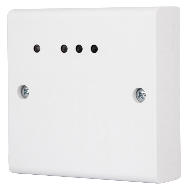
The external appearance of the U‑PROX IC E controller is shown in Figure 1.
Figure 1. External Appearance of U‑PROX IC E
The layout of jumpers, buttons, and connectors on the controller board is shown in Figure 2.
Figure 2. Controller Board Layout
Function of the Controller’s Contacts, Jumpers, and Buttons
| Name | Function |
|---|---|
| +12V | Connection for external power supply |
| GND | Ground |
| A+ | RS‑485 bus for connecting expansion modules |
| USB Port (micro B) | Used for initial network configuration and firmware updates |
| Jumper BAT | Enables the backup battery for clock and memory support |
| FUNC Button | Service button for factory reset |
| Jumpers TERM | Sets termination resistors for the RS‑485 bus |
Audio‑visual Indication of the Controller
The controller’s indicator LEDs (from left to right) are as follows:
- Link LED: Lit when the Ethernet cable is properly connected.
- Act LED: Blinks rapidly when data exchange is in progress.
- Bi‑color LED (LED):
- Normal mode: Red – two short pulses per second indicate no connection to the ACS server; Green – one short pulse per second indicates a normal connection.
- Bootloader mode: Rapid red blinking indicates the device is loading.
Audio‑visual Indication of Connected Readers
Access mode indication is performed by readers connected via the RS‑485 bus (using U‑PROX WRS485, for example). Each controller’s indication can be individually configured via the ACS software. The default indications are as follows:
| Mode | Reader Indication |
|---|---|
| Normal mode | No sound; red blink once per second |
| PIN Code Control Enabled | No sound; red-green blink once per second |
| Free Passage | No sound; green-yellow blink once per second |
| Lockout | No sound; red-yellow blink once per second |
| Alarm | No sound; continuous red light |
| Card Registration | No sound; green blink once per second |
| Initialization | No sound; no light indication |
| Loading | No sound; continuous red light |
| Waiting for PIN Input | No sound; yellow blink once per second |
| Access Granted | No sound; continuous green light |
| Access Denied | Continuous sound; continuous red light |
Controller Operation
Controllers are shipped in an un‑loaded (factory default) state. In this state, the bi‑color LED blinks red twice per second. To operate the controller in an ACS, network settings must be loaded using the “Configurator” software or via auto‑configuration.
Once configured, the controller enters “Normal” mode.
The controller can be reset to the un‑loaded state either by a computer command or by the procedure described in the Service and Maintenance section.
“Normal” Mode
“Normal” mode is the primary operating mode in which the controller grants or denies access based on presented identifiers.
Access on Identifier Presentation: To gain access to a floor, a user presents a contactless identifier to a reader. If the identifier is registered, the controller, via the relays of the U‑PROX RM modules, activates the corresponding elevator floor buttons for which access is allowed.
Access on Identifier and PIN Code Presentation: After presenting a registered identifier, the controller checks if a PIN code is required. If so, it enters a waiting state for PIN entry. Upon correct PIN input, the actuator is activated.
Access Denial: Access may be denied if:
- The controller is in an un‑loaded state,
- The card is not registered,
- The card’s validity period has expired,
- Access is currently prohibited by schedule or day of the week,
- There is an attempt of repeated passage when the anti‑passback function is enabled,
- An identifier marked as lost or blocked is presented,
- The controller is in “Alarm” mode,
- The controller is in “Lockout” mode,
- The activation time for a temporary card has not yet begun,
- The passage counter for a temporary (visitor) card is exhausted.
“Alarm” Mode
The access point enters “Alarm” mode when the controller’s case is opened, when an identifier marked as lost is presented, or when an unregistered identifier is repeatedly attempted (if the function is enabled). In “Alarm” mode, access is blocked. To cancel the alarm mode, either present an identifier marked for “Alarm Cancellation” or issue a command from the computer.
“Free Passage” Mode
In some emergency situations (e.g., fire, earthquake), it is necessary to open doors (either all or a subset) for free passage. In this case, the controller enters “Free Passage” mode by command from the computer. While in “Free Passage” mode, the floor selection buttons are not blocked; the controller logs all identifier presentations and code entries as “Access Granted,” regardless of anti‑passback or schedule restrictions. This is used to monitor personnel presence during emergencies.
“Lockout” Mode
If a situation arises requiring that all doors be locked for all users, the controller enters “Lockout” mode. In this mode, access to a floor is granted only to identifiers with the “Security Service” attribute. When a normal card is presented, the event “Access Denied – Lockout” is logged. Only a card with the “Security Service” attribute will allow access and log “Access Granted – Lockout.”
Properties of Identifiers (Cards)
Code (Electronic Card Code): Each card has a unique code assigned during manufacturing, containing 6 to 16 hexadecimal digits.
PIN Code: A supplementary code for the card consisting of exactly six decimal digits. When a card is presented, the built-in keypad prompts for the PIN; if the correct PIN is entered (followed by the “#” key), the U‑PROX RM modules’ relays activate the elevator buttons corresponding to allowed floors. Otherwise, a warning is issued and the event “Incorrect PIN” is logged.
Validity Period: The expiration date of the card.
Alarm Cancellation: When a card with the alarm cancellation right is presented at an access point in alarm mode, the controller logs “Alarm Cancelled” and resets the door to normal mode. If a card without this right is presented, the alarm remains active and “Access Denied – Alarm” is logged.
Security Service: Grants the right to access locked doors. In Lockout mode, only cards with the “Security Service” attribute are allowed access.
VIP: Grants unconditional access except when the device is in Lockout mode. Such cards may be assigned any schedule, are not subject to anti‑passback or validity restrictions, and may include a PIN code.
Operation of the Communicator
The U‑PROX IC E controller operates automatically. After its configuration is loaded from the server, it processes data from the connected readers (via RS‑485 and U‑PROX RM modules), applies the access rules for presented cards, and sends access event notifications to the ACS server.
The communicator works in notification mode, meaning that whenever an event (access, zone violation) occurs, data is immediately transmitted to the ACS server.
The U‑PROX IC E controller can be connected to a computer network via a wired Ethernet connection, allowing it to operate both within the local network and via the Internet (see Figure 3).
Figure 3. Example Network Configuration
For added security when networking a central office and branch offices, VPN technology is recommended, along with routers featuring dual, heterogeneous Internet channels for redundancy.
System Deployment
The use of existing network infrastructure and standard protocols (e.g., DHCP) enables the “plug‑and‑play” principle. Auto‑configuration of the ACS server address in the devices greatly simplifies system deployment.
System Deployment Procedure: (See Figure 4)
Figure 4. System Deployment
- Upon power‑up, the controller checks whether DHCP is enabled (device IP is 0.0.0.0) or if it has obtained a static IP address.
- If DHCP is enabled, the dynamic IP address assignment procedure is initiated.
- If the ACS server address (IP or DNS) is not set, the controller enters auto‑configuration mode:
- The device broadcasts data packets announcing itself as a new device on the local network.
- This broadcast is limited to the peer‑to‑peer local network and active networking equipment; for complex networks, the ACS server IP must be set manually.
- When a packet from a new device is received, the system operator is alerted and must add the device to the database.
- After the device is added, it receives a response from the ACS server, stores the server address in its settings, and stops broadcasting.
- If the server address changes, the device will auto‑configure again, but communication will only be possible with the ACS to which it is bound.
- To unbind the controller from an ACS, reset it to factory settings.
Interaction with Elevator Equipment
The U‑PROX IC E controller connects to elevator equipment via the RS‑485 bus using expansion modules (U‑PROX RM and U‑PROX WRS485) or via U‑PROX SE series readers. Typically, the reader is mounted in the elevator cab.
The relay outputs of the U‑PROX RM module are connected to the elevator floor selection buttons. In the de‑energized state, the U‑PROX RM module allows the buttons to operate.
Cables (from inputs Z1–Z8) can be connected to provide feedback from the elevator automation to detect when a floor button is pressed. If such feedback is used, a message “Floor Access Granted” is generated after the button is pressed.
Remote Floor Access Provision
Remote control cables (connected to inputs Z1–Z8) can be used to provide remote access—for example, from a security post. When the floor button is pressed at the security post, a message “Floor Opened by Button” is generated.
Emergency Unlocking of the Elevator Control Panel
Each relay module is equipped with an EMRG input. Normally, the cable connected to this input should be short‑circuited to ground (GND). If the cable is broken, the elevator control module disconnects and full access to the floor selection panel is restored, allowing a user to select any floor without presenting an identifier.
Figure 5. Connection Diagram
Connecting Expansion Modules via the RS‑485 Bus
The RS‑485 interface is used to connect expansion modules to the U‑PROX IC E controller. The RS‑485 bus can extend up to 1200 meters without additional equipment. Termination resistors must be enabled on the first and last devices on the bus by setting the termination jumpers (see Figure 6).
When connecting expansion modules:
- U‑PROX RM modules cannot be connected at the ends of the RS‑485 bus since they lack termination jumpers.
- Each U‑PROX RM module must have a unique ID set via its DIP switches (range 0 to 7).
- You may use a U‑PROX WRS485 module (with an attached Wiegand reader) or a U‑PROX mini 485 reader.
- Set the ID of the U‑PROX WRS485 module to 0 via its DIP switch.
- Set the operating mode of the U‑PROX WRS485 module to “slave” by switching the DIR (No.1) to the “OFF” position.
Figure 6. Connection of the Controller and Expansion Modules to the Data Bus
Communication
For communication with the ACS server, the U‑PROX IC E controller can use a wired computer network. The device can be configured either via auto‑configuration or manually using the “Configurator” software on a PC.
Proper configuration ensures:
- Assignment of a static or dynamic (DHCP) IP address to the device;
- Operation with the ACS server using an IP or DNS address;
- Internet connectivity, with redundancy provided by a secondary router if necessary.
The controller’s communicator works in notification mode – when an event (access or zone violation) occurs, data is sent to the ACS server.
Additionally, the controller protects against unauthorized access by encrypting data packets with a 256‑bit key, verifying its unique serial number, and monitoring the communication channel with periodic test signals.
Wired Computer Network (Ethernet)
The Ethernet interface is used to connect system components into a network. Ethernet cables without additional equipment can run up to 100 meters while providing data transfer speeds of up to 100 Mbps.
Figure 7. Examples of Ethernet Cable Connections
Two examples are provided: direct crimping for connection to a switch or router, and crossover wiring for connection to a computer.
- Direct Crimping:
- White‑yellow – white‑yellow
- Yellow – yellow
- White‑green – white‑green
- Blue – blue
- White‑blue – white‑blue
- Green – green
- White‑brown – white‑brown
- Brown – brown
- Crossover Wiring:
- White‑yellow – white‑green
- Yellow – green
- White‑green – white‑yellow
- Blue – blue
- White‑blue – white‑blue
- Green – yellow
- White‑brown – white‑brown
- Brown – brown
During Ethernet configuration, set the following parameters (if DHCP is not used):
- Device IP address
- Subnet mask
- Gateway IP address (for Internet 1, optionally for local networks)
- Gateway IP address for Internet 2 (optional)
- Primary DNS server IP (if domain name resolution is used)
- Secondary DNS server IP (optional)
Additionally, configure communication with the ACS server (if auto‑configuration is not used):
- ACS server IP or DNS address
- Access ports (read and write ports)
- Frequency of test signal transmissions for channel monitoring
Controller Programming Procedure
Software: Use the “Configurator” software via the USB port to program the controller.
Procedure:
- Determine the configuration mode: auto‑configuration or manual.
- If manual configuration is selected, enter the initial network parameters:
- Server settings: IP or DNS address of the ACS server, access ports (read/write)
- If DHCP is available, some steps may be skipped.
- Device settings: IP address, subnet mask, DNS, gateway, etc.
- Connect and register the controller using the ACS software (refer to the ACS manual).
- After the configuration is formed and loaded from the ACS software, the device is ready for operation.
Service and Maintenance
Factory Reset
To reset the controller to factory settings, follow these steps:
- Disconnect the controller’s power supply.
- Press and hold the FUNC button.
- Reconnect the power supply.
- Wait 10 seconds until the LED lights red, then release the FUNC button.
- The LED will flash red 6 times to indicate that the factory reset is complete.
Switching to Programming Mode
To put the controller into programming mode, simply connect it to a computer via the USB cable and then configure it using the “Configurator” software.
Firmware Update
- Connect the USB cable first to the computer, then to the controller.
- Using the designated firmware update software, perform the firmware update.
- After the firmware is loaded, wait 25–30 seconds before disconnecting; the controller will then be ready for operation.
Factory Settings
The factory settings are as follows:
- DHCP enabled (no static IP assigned)
- No ACS server address specified (auto‑configuration enabled)
Maintenance and Repair
Warranty and post‑warranty service for U‑PROX IC E controllers is provided only by persons or organizations authorized by the manufacturer.
Warranty Obligations
The manufacturer guarantees that the U‑PROX IC E controller conforms to the parameters described in this manual, provided that storage and operating conditions comply with the instructions herein.
Storage Warranty: 6 months from the date of manufacture.
Operational Warranty: 12 months from the date the device is put into service.
Device supply, personnel training, installation, commissioning, and warranty service for the U‑PROX IC E controller are provided by the manufacturer or by authorized organizations.
If a defect due to the manufacturer is detected, the authorized organization will remedy it within 10 days of notification.
If commissioning is performed by an unauthorized organization, the consumer forfeits warranty service.
Warranty repairs will not be performed if the device fails due to improper connection, non‑compliance with this manual, mechanical damage, or force majeure.
The manufacturer reserves the right to make design changes that do not affect the main technical characteristics or reliability of the product.
© 2024 Limited Liability Company Integrated Technical Vision
www.u-prox.systems
Download
FAQ
-
- Connect wires D0 (green) and D1 (white) with each other
- Apply power to the reader
- Connect to the reader with application U-Prox Config installed on smartphone.
- Select “Settings”
- Set a password
- Go back
- Press “Save Settings”
- Press “Disconnect”
-
The control panes is the “brain” of the system, which determines whether or not the owner of the identifier is allowed to enter the door.
It has a built-in memory that stores identifier codes with a list of access rights for each of them.
When a person presents (brings to the reader) an identifier, the code read from it is compared with the one stored in the database, on the basis of which a decision is made to open the door.
-
A reader is a device that reads the code (key) of the identifier and transmits it to the controller.
-
PACS — Physical Access Control System —an access control and management system is a set of hardware and software control and management tools.
The main goal is to restrict and register the entry-exit of objects in a given area through “points of passage”: doors, gates, etc.
The main task is to control access to a given territory (who to let in, at what time and to what territory), including also:
- restricting access to a given territory;
- identification of a person who has access to a given territory.
-
An identifier is the basic element of an access control system that stores a code.
Each client is assigned a specific key (code), which serves to determine the owner’s rights – identification.
A card, a key fob, a tag can perform the function of an identifier.
-
Areas of application have a wide range of ACS:
- company offices, business centers;
- banks;
- educational institutions (schools, technical schools, universities);
- industrial enterprises;
- protected areas;
- parking lots;
- places of passage of vehicles;
- private houses;
- residential complexes;
- cottages;
- hotels;
- public institutions (sports complexes, museums, metro, etc.)
-
Everything that is U-PROX, from the idea to the engineering implementation is done exclusively in Ukraine.
-
Open formats JSON and SOAP (XML) allow interaction between different applications, exchange data with access control systems and create applications that complement and extend the standard functionality of the U-PROX Web system.
API capabilities:
- Secure data exchange over a computer network.
- WEB service – the opportunity to interact with any platform and programming environment for SOAP and JSON protocols.
- Implementation of the user interface using the API.
- The ability to integrate with other systems and applications implemented by third-party developers.
-
You can buy U-Prox equipment from our partners.
-
U-PROX WEB provides a full range of solutions for quick installation, configuration and daily use of IP ACS by enterprises of any size, from a small office to a large company with many branches.
U-PROX Web has a full-featured web interface with fine-tuning of all ACS capabilities and provides the ability to monitor events, configure equipment, manage personnel access, and generate reports.