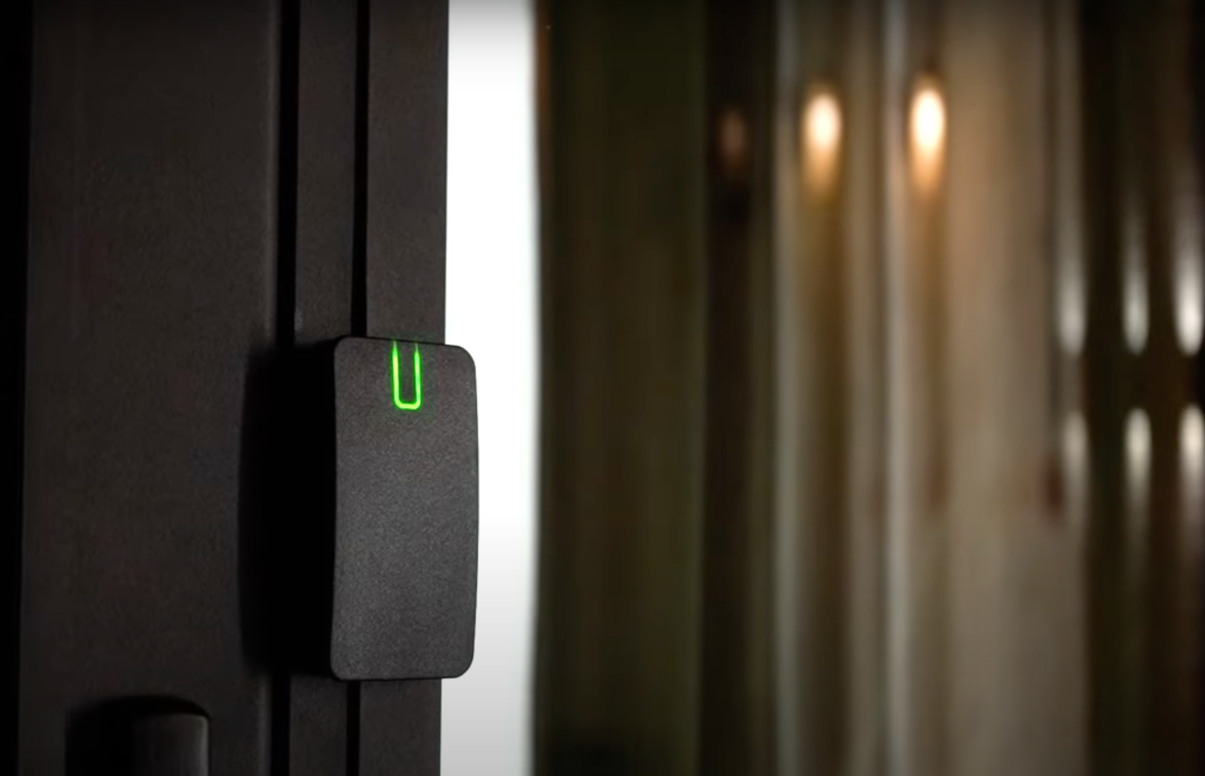
U-PROX IP400
Fully functional access control panel with IP network capability

32K
identifiers

2 doors with reader and REX button

one door with two readers
47К
events
Initial setup via USB

Two Wiegand interfaces

ACS Cloud

Network interface

IP-based network control panel
Universal IP-based access control panel with two Wiegand readers
Powerful IP control panel
- Operation in IP networks
- Supports DHCP, DNS, works through NAT
- 32,000 cards
- 47,000 events
- Local and Global AntiPassBack
- Designed for maximum autonomy


Universal work patterns
- Up to 2 single-sided doors
- Double-sided door
- Turnstile
- Turnstile with pulse control
- Connecting biometric readers, alcohol testers, gateway system, etc.
Various supply options
- Device in a metal case, built-in backup power supply
- Control panel board only
- Firmware to support 65000 identifiers (without local antiPassBack)

Certificates
NEW PRODUCTS


Want to buy?
Contact partner companies to purchase or install security and automation devices.
Want to sell?
Become an official distributor, reseller or installer of U-PROX security and safety systems.
TECHNICAL SPECIFICATIONS
| Inputs | end-of-line resistor supervised inputs (EOL - 2 kΩ) |
|---|---|
| Outputs (Relays) |
Two relays (NO, NC, COM) 5 A @ 24 V Two relays (NO, COM) 1 A @ 24 V |
| Connection | Ethernet 100Mbit |
| Memory |
IDs - 32 000 Events - 47 000 Weekly schedules - 250 Time zones - 250 Holidays - 250 |
| Power | +10,8...+15 V DC, consommation < 160 mA @12V |
| Dimensions |
The device in the case - 240 х 276 x 96.5 mm Board - 122 x 89 x 21 mm |
| Weight |
The device in the case - 2,1 kg Board - 0,15 kg |
| Case colour | white |
| Case material | metal |
| Operating temperature range | from -10°C to +55°C |
| Configuration | USB port for initial setup |
| Complete set |
1. U-PROX IP400; 2. Mounting kit; 3. Quick start guide |
Color


U-PROX IP400 User manual
Controller Description
The U-PROX IP400 controller is designed for use in access control systems (ACS) of various scales — from small officeaccess control systems to access control solutions for large enterprises. Within an ACS, controllers are interconnected via a computer network.
The devices can be used to control bidirectional and unidirectional doors, turnstiles, and to implement mantrap systems. Using ACS software, the access controller can be integrated with video surveillance systems, biometric readers, breathalyzers, security systems, and other third-party solutions.
The controller allows organizing access to two separate premises or to a single premise with both entry and exit control. When both entry and exit are controlled simultaneously, the Anti-Passback (anti-duplication) function is available.
The controller operates with two readers connected via the Wiegand interface.
U-PROX IP400 processes the information received from the reader(s) and, using four relays, controls effective devices(e.g. locks, sirens). The presence of eight additional inputs with different programming options provides continuous monitoring of eight security zones (with current monitoring). The controller can operate both autonomously and as part of a computer network. To combine controllers into an access control system (ACS), an Ethernet interface (wired computer network) is used.
The U-PROX IP400 device is available in two versions::
- U-PROX IP400H — a device housed in a metal enclosure with an uninterruptible power supply (UPS), a batterycompartment, and a fuse block.
- U-PROX IP400EM — controller board only.
Each kit includes resistors (8 pcs) for security inputs and shunt diodes (2 pcs).
Starting from spring 2025, all IP400 controllers feature the following updates:
The U-PROX IP400H power supply unit is designed to operate with lead-acid (AGM) and lithium iron phosphate(LiFePO₄) batteries and provides:
- a dedicated battery charging output with a charging current of 1.5 A;
- a separate output for powering devices of 2.8 A;
- extended backup operation time when using batteries with a capacity of 7–9 Ah.
The controller is powered by a 12 V DC power supply. It consumes up to 160 mA without additional loads. The ripplevoltage of the DC power supply shall not exceed 500 mV.
The controller supports network configuration and firmware updates via a standard USB port (micro-USB Type C).
Attention! When configuring the controller, it is recommended to connect it to the computer using a USB Type-C cable viaUSB 2.0 or USB 3.0 ports.
USB 3.1 and USB 3.2 ports are not compatible, and the connection will not be established.
Controller Construction

- Device housing
- Housing doors
- Tamper (opening sensor)
- Controller unit
- Power supply unit
Device Diagram
The layout on the controller board of jumpers, buttons, and removable terminal blocks with connectors, and their functions
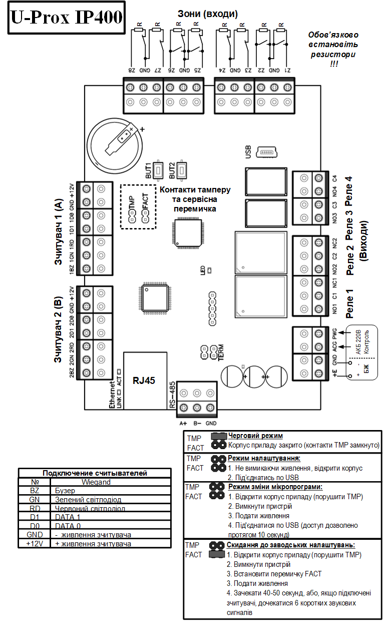
Contact Assignment
| Contact | Function |
|---|---|
| Z1 | Input 1, contact for connecting cables |
| Z2 | Input 2, contact for connecting cables |
| Z3 | Input 3, contact for connecting cables |
| Z4 | Input 4, contact for connecting cables |
| Z5 | Input 5, contact for connecting cables |
| Z6 | Input 6, contact for connecting cables |
| Z7 | Input 7, contact for connecting cables |
| Z8 | Input 8, contact for connecting cables |
| GND | Common contact (ground) |
| NC1 | Relay 1 contacts, normally closed |
| NO1 | Relay 1 contacts, normally open |
| C1 | Relay 1 common contact |
| NC2 | Relay 2 contacts, normally closed |
| NO2 | Relay 2 contacts, normally open |
| C2 | Relay 2 common contact |
| NO3 | Relay 3 contacts, normally open |
| C3 | Relay 3 common contact |
| NO4 | Relay 4 contacts, normally open |
| C4 | Relay 4 common contact |
| 1BZ | Reader 1 connection (access point A), buzzer |
| 1GN | Reader 1 connection (access point A), green LED |
| 1RD | Reader 1 connection (access point A), red LED |
| 1D1 | Reader 1 connection (access point A), Data 1 |
| 1D0 | Reader 1 connection (access point A), Data 0 |
| +12V | Reader 1 connection (access point A), Power |
| GND | Common contact (ground) |
| 2BZ | Reader 2 connection (access point B), buzzer |
| 2GN | Reader 2 connection (access point B), green LED |
| 2RD | Reader 2 connection (access point B), red LED |
| 2D1 | Reader 2 connection (access point B), Data 1 |
| 2D0 | Reader 2 connection (access point B), Data 0 |
| +12V | Reader 2 connection (access point B), Power |
| GND | Common contact (ground) |
| E+ | External power source connection (+) |
| GND | External power source connection (–) |
| ACG | Battery status: normal |
| PWG | 220V mains: normal |
| TMP | Housing opening sensor, tamper |
| FACT | Reset to factory settings |
| BUT1 | Access request button for access point A |
| BUT2 | Access request button for access point B |
| USB Type C | USB port used for initial network configuration and device firmware updates |
Audio-Visual Indication of the Controller
| LED | Description |
|---|---|
| LED, periodic blinking |
|
| LED, rapid blinking |
|
| Link, lit |
|
| Link, unlit |
|
| Act, rapid blinking |
|
Audio-Visual Indication of the Controller Readers
The indication of access modes is performed by the controller’s readers. Each controller can have its indication individually configured via the ACS software. The settings are presented in a table showing combinations of sound and light indications.
Controller Operation
Controllers are shipped in an unprogrammed state with factory settings. In this state, the controller’s yellow LED blinks once per second. To operate the controller within an ACS, network settings must be loaded into the device using the “Configurator” software.
It is recommended to install the supplied resistors on all controller inputs.
After the settings are loaded—and provided that all inputs are intact—the controller enters the “Normal” mode.
The controller can manage two independent access points. An access point can be configured in one of four modes: “Normal”, “Alarm”, “Lockout”, and “Free Passage”. The highest priority is given to the “Free Passage” mode, as this mode is activated in the event of a fire; followed by “Lockout”, “Alarm”, and “Normal”.
“Normal” Mode
The Normal mode is the controller’s primary operating mode. In this mode, the controller either grants or denies access to identifier holders.
Access on Presentation of an Identifier
To gain entry, the user presents a contactless identifier to the reader. If the identifier is registered and access is currently allowed, the door will open (the controller activates the actuating mechanism).
Access on Presentation of an Identifier and PIN Code
After presenting a registered identifier, the controller checks whether a PIN code is required. If so, it enters a state waiting for PIN code entry. Upon correct entry of the PIN code, the access point is opened (the actuating mechanism is activated).
Access via an Access Request Button (Remote Door Opening)
For exit from a premises with a single-sided access point or for allowing visitor entry, an access request button is used. Pressing and releasing the button opens the access point (activating the actuating mechanism).
Access Denial on Presentation of an Identifier
Access may be denied for the following reasons:
- The controller is in an unprogrammed state;
- The card is not registered in the controller;
- The card’s validity period has expired;
- Access is currently prohibited based on the schedule and/or day of the week;
- An attempt is made to re-enter when the “Anti-passback” function is active;
- The presented identifier is registered as lost or blocked;
- The controller is in “Alarm” mode;
- The controller is in “Lockout” mode;
- The validity period for a temporary card has not yet begun;
- The passage counter for a visitor’s temporary card has been exhausted.
“Alarm” Mode
An access point enters “Alarm” mode in cases of unauthorized entry (forced entry), tampering with the controller housing, presentation of an identifier marked as lost, if the door remains open too long (exceeding the allowed open time), or if the identifier selection function is activated.
In “Alarm” mode, the controller activates outputs designated as ALARM and SIREN. The alarm output remains active until the “Alarm” mode is deactivated, and the siren output is programmed with a set duration for the siren sound.
If an access point is in “Alarm” mode, passage through it is blocked. The door may only be opened by pressing the exit request button.
“Alarm” mode can be deactivated by presenting an identifier marked for “Alarm Cancellation” or via a command from the computer.
“Free Passage” Mode
There are situations in an ACS when it is necessary to open the door for free passage of people—for example, in the event of a fire, earthquake, or other extreme situations. For such cases, the controller provides a “Free Passage” mode.
An access point enters “Free Passage” mode either by a command from an operator via the computer or by a break in the cable designated as FREE PASSAGE. The access point remains in “Free Passage” mode as long as the free passage cable remains broken (if the cable is broken, the free passage state cannot be cancelled by operator command).
The controller allows configuring the cable as a Free Passage function for access point A, access point B, or both (A+B).
While the access point is in “Free Passage” mode, the lock remains open continuously, and the controller logs every identifier presentation and code entry as an “Access Granted” event—regardless of the anti-passback, schedule, and other card attributes. This is used to track personnel presence during extreme situations.
When using locking devices with mechanical reactivation, it is essential to monitor the door status. Such devices are deactivated by an impulse of current and remain open until the door is closed. Upon door closure, the locking device returns to the locked state. In “Free Passage” mode, the controller checks the door contact and, after each door closure, issues another unlocking impulse to the lock.
When operating the controller without a door contact (reed switch), using an “impulse” output type for unlocking the door is not recommended. In this case, the “Free Passage” mode will not function correctly – it will be impossible to open the door without presenting an identifier.
“Lockout” Mode
If a situation arises that requires the door to be blocked for all system users, the controller enters “Lockout” mode. When an access point is in “Lockout” mode, only identifiers with the “Security Service” attribute are granted access. In this state, the door cannot be opened by pressing the exit request button.
An access point enters “Lockout” mode either by a command from the computer or by a break in the cable designated as LOCKOUT. The access point remains in “Lockout” mode as long as the lockout cable remains broken (if the cable is broken, the lockout state cannot be cancelled by operator command).
The controller allows configuring the cable for the Lockout function for access point A, access point B, or both (A+B).
Usage Options and Operating Modes of the Outputs
All outputs of the controller can be programmed for various uses: to control a lock, siren, alarm, or as a programmable output. In addition, each output can be programmed with an operating mode: continuous (the output remains active as long as the condition is met, for example, while in “Alarm” mode), impulse (the output is activated for a set time), trigger (the output is activated on the first event and then deactivated on the next, and so on), or manual (the output is activated or deactivated by separate commands).
Operation of Identifiers (Cards)
Code (Electronic Card Code)
Each card has its unique code assigned during manufacturing. It consists of 10 hexadecimal digits.
PIN Code
This is an additional code assigned to the card. It must consist solely of six decimal digits. It can be used in conjunction with readers that have an integrated keypad (for example U-PROX SL/SE keypad).
After presenting the card to the reader’s built-in keypad, the PIN code must be entered and the “#” button pressed. If the correct PIN code is entered, the controller unlocks the door and grants access. Otherwise, the controller issues a warning signal, logs an “Incorrect PIN” event, and the door remains locked.
Validity Period
This is the expiration date of the card’s validity.
Alarm Cancellation
If a card designated for alarm cancellation is presented to a reader at a door in an alarm state, the controller logs an event “Alarm Cancelled” and returns the door to the normal state. If a card without alarm cancellation rights is presented, the door remains in its current state and an event “Access Denied. Alarm State” is recorded.
Security Service
This attribute grants the right to access even through locked doors. If the door is in “Lockout” mode, presenting a regular card will result in an “Access Denied. Lockout State” event. However, if a card with the “Security Service” attribute is presented, the controller grants access and logs an event “Access Granted. Lockout State”.
VIP
This attribute allows access at all times and in all areas, except when the door is in Lockout mode. A card with this attribute can be assigned any schedule and is not subject to anti-passback or validity period restrictions. It may also include a PIN code. If the door is in “Lockout” mode, even a VIP identifier will not be granted access.
Anti-passback Disabled
This setting allows access without considering the anti-passback function. Such a card is granted access regardless of the direction of the previous passage, but still subject to the assigned schedule and other card attributes.
Operation of the Communicator
The U‑PROX IP400 controller operates in an automatic mode. After loading data from the server, it enforces access rules for the presented cards and sends access event notifications to the ACS server.
The controller’s communicator works in notification mode, meaning that when an event (passage or zone violation) occurs, data is transmitted to the ACS server.
The U‑PROX IP400 controller can be connected to a computer network via a wired Ethernet connection. In this case, it supports both operation within the enterprise’s local network, as well as via the Internet. 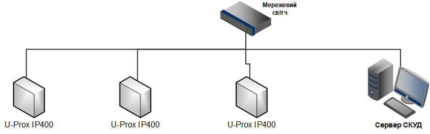
It also supports Internet connectivity, allowing for distributed access control systems of any scale. 
Device configuration can be performed either via auto‑configuration or manually from a PC using the “Configurator” software. When properly configured, the following is ensured:
- The device is assigned either a static or dynamic (DHCP) IP address;
- It operates with either an IP address or a DNS (domain name) address for the ACS server;
- It supports Internet operation (for servicing remote branches) with the possibility of redundant Internet paths through a secondary router;
The controller operates in automatic mode – after loading data from the server, it enforces access rules for the cards and sends corresponding notifications to the server.
The communicator functions in notification mode, meaning that when an event occurs (such as passage or a zone violation), data is transmitted to the ACS server.
When operating on a computer network, the controller ensures protection against unauthorized interference by encrypting data packets using a 256‑bit key and by verifying the unique serial number of the device, as well as by monitoring the communication channel through periodic test signals from the device.
Local Network Operation Algorithm
- Upon power-up, the controller checks whether DHCP is enabled (device IP address is 0.0.0.0) or if the device has obtained a static IP address;
- If DHCP is enabled, the dynamic IP address assignment procedure is initiated;
- The IP address status is periodically updated (maintaining the reserved IP address if DHCP is enabled);
- The availability of the ACS server and the U‑PROX IC A controller is determined (via IP or DNS name);
- Periodic test signals are sent;
- Access events are transmitted;
- The controller waits for commands.
Internet Network Operation Algorithm (Local Wired Network)
- Upon power-up, the controller checks whether DHCP is enabled (device IP address is 0.0.0.0) or if it has obtained a static IP address;
- If DHCP is enabled, the dynamic IP address assignment procedure is initiated;
- The IP address status is periodically updated (maintaining the reserved IP address if DHCP is enabled);
- The possibility of Internet access is determined (by checking the availability of the routers’ IP addresses);
- The availability of the ACS server and the U‑PROX IC A controller is determined (via IP or DNS name);
- Periodic test signals are sent;
- Access events are transmitted;
- The controller waits for commands.
Auto‑Configuration of Controllers in a Peer-to‑Peer Network
By using the existing network infrastructure and standard network protocols (such as DHCP), the “plug‑and‑play” principle is implemented. The auto‑configuration mode for the server address on the devices greatly simplifies the deployment of the access control system.
- After power‑up, the controller checks whether DHCP is enabled (device IP address is 0.0.0.0) or if it has obtained a static IP address;
- If DHCP is enabled, the dynamic IP address assignment procedure is initiated;
- If no ACS server address (IP or DNS name) is set, the controller enters auto‑configuration mode:
- The device broadcasts data packets announcing itself as a new device on the local network.
- Upon receiving a packet from a new device, the system operator is notified. The operator must then add the device to the database.
- After the device is added to the database, it receives a response packet from the ACS server. The server address is then stored in the controller’s settings, and the broadcast stops.
- After the controller’s parameters are configured in the database, the operator must load the device. The device will then be linked to that ACS, preventing unauthorized control interception.
- If the server address changes, the device will re‑auto‑configure; however, data exchange will only be possible with the ACS to which the device is already bound.
- If necessary, the controller can be reset to factory settings to cancel its binding.
Although this broadcast is limited to the peer-to‑peer local network and active network equipment, for networks with complex topologies the ACS server’s IP address must be set manually.
Each U-PROX system has a unique encryption key used to protect network communication and the controller’s memory. To reset the encryption key, the controller must be restored to factory settings
Global Anti‑passback
The U‑PROX IP400 controller can operate as part of a global anti‑passback system. In this case, a master controller of the U‑PROX IC A series tracks the location of a person based on their passage through a door, receiving data from U‑PROX IP400 controllers. The global anti‑passback is based on zone‑based anti‑passback. The premises are divided into rooms – access zones. With such a division, entering another zone is considered an exit from the previous one. Passage to a zone is possible through different doors. The anti‑passback controller tracks employee movements from one zone to another by receiving data from the access controllers. 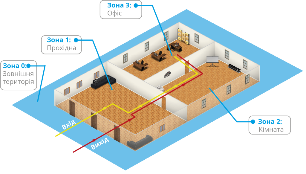
Initially, an employee’s location is “Undefined” and only after the first presentation of an identifier to a reader is their location recorded by the U‑PROX IC A controller. The “Undefined” status is assigned during the registration of a new employee or after the operator issues a “General Location Reset” command.
Using the global anti‑passback system, repeated passages, card duplication, unauthorized entry (unexpected presence inside), sharing of identifiers, etc., can be prevented. 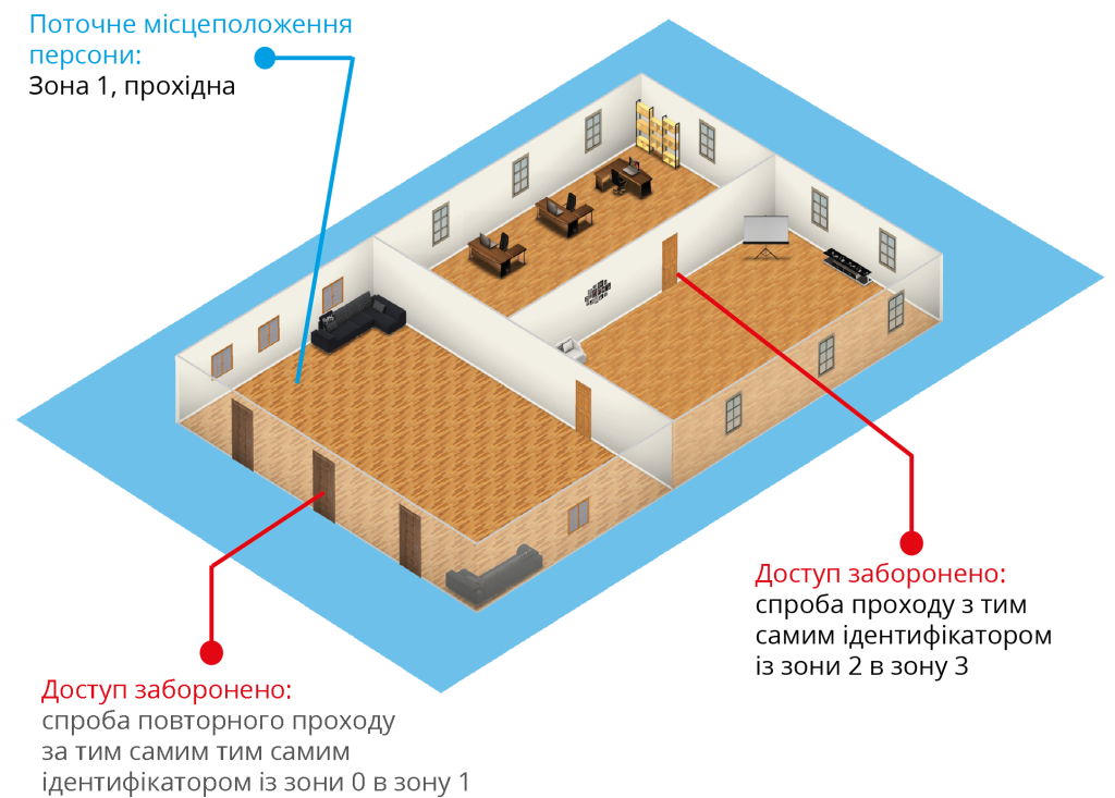
If communication with the ACS controller is lost, if the door is forced open, or if the door switches to free passage, the anti‑passback controller groups the access zones into one, assuming that personnel may be present in both zones. When the door or connection is restored, the zones are separated again. The actual location of personnel is then determined by subsequent presentations of the identifier to the reader. 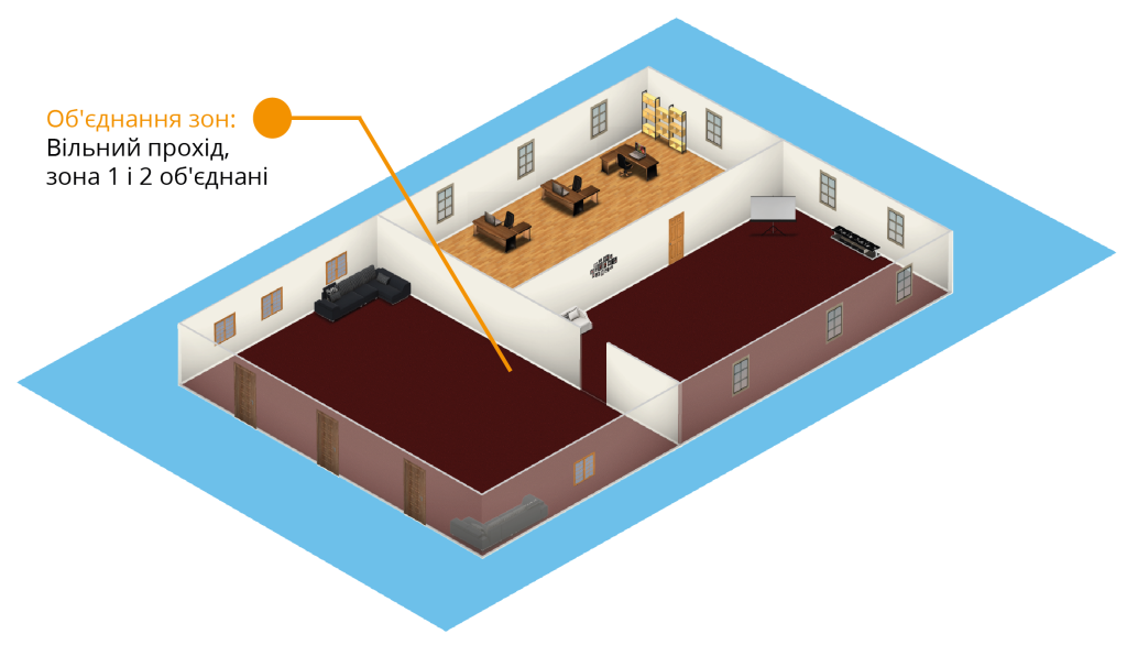
If communication with the U‑PROX IC A controller is lost, U‑PROX IP400 access controllers can be configured to behave in one of two ways:
- Block all access
- Grant access according to the locally stored person location data from the anti‑passback function
Requirements for Configuring the U‑PROX IC A Controller
- The controller must have a static (fixed) IP address.
Requirements for Configuring U‑PROX IP400 Controllers
- Only controllers with double‑sided doors (entry and exit by identifier presentation) participate in global anti‑passback.
- The first ACS server address in the device’s communication settings must be the address of the computer running the U‑PROX IP server software.
- The second ACS server address in the communication settings must be the address of the U‑PROX IC A controller.
- The ACS must have the “General” anti‑passback mode enabled for the doors.
- The access controller in the ACS must have the master anti‑passback controller specified, along with the corresponding reaction to communication loss.
U‑PROX IP400 controllers send access event notifications to two addresses simultaneously. The first address is the ACS server, where events are displayed and stored in the application’s database. The second address is the U‑PROX IC A controller, which responds with a command to either deny or grant access.
After presenting an identifier, the delay in granting or denying access may be up to 1 second depending on the network topology and bandwidth.
Operating Procedure for the Device
The controller is supplied in a metal housing with its power source. The overall dimensions of the device are shown in the illustration below. 
Mounting Recommendations
The controller should be installed in a location that is accessible for maintenance.
To mount the controller on a wall, perform the following steps:
- Open the housing cover, hold the housing against the intended mounting location, and mark the drill holes;
- Run the cables through the holes in the housing wall;
- Secure the controller housing;
- Connect the cables.
Connection Procedure
- Before installation, perform the initial configuration (set the network parameters) of the controller using the “Configurator” utility via the USB port.
- At the installation site, prepare by marking and drilling the necessary holes.
- If required, run the cable from the power supply unit.
- Connect the cable from the actuating device (lock).
- Install the external readers and connect their cables.
- Run the cables from the sensors/buttons.
- Connect the Ethernet cable.
- Route the installation cables within the wall.
- Mount and secure the controller housing.
- Connect the wiring of the power supply, lock, reader, and controller inputs with cables as specified in the following sections.
- Connect the Ethernet cable.
- Close the cover and secure it with a screw.
- Register the controller in the ACS (according to the ACS instructions).
- Using the ACS, perform a full load (configure inputs, outputs, schedules, identifiers, etc.) of the controller.
- The device is now ready for operation.
Connecting the Readers
The controller has two Wiegand interface ports for connecting readers. Readers with a Wiegand interface can work together with the controller. 
Wire color correspondence:
- White – Data 1
- Green – Data 0
- Blue – Buzzer activation
- Brown – Red indicator activation
- Orange – Green indicator activation
- Black – GND
- Red – +12V
When using readers from different manufacturers, the wire colors may differ. Refer to the reader’s user manual for the correct color correspondence.
The current consumption of each external reader connected to the “+12V” terminal must not exceed 150 mA. When connecting long‑range readers with current consumption above 150 mA, power must be supplied from a separate source.
Connecting the Cables (Inputs)
The controller has eight inputs for connecting cables with current monitoring. The function of each input is set during the controller’s programming. The following functions are possible for the inputs:
- Passage sensor (door contact)
- Exit request button
- Passage sensor (door contact) + exit request button
- Free Passage (A, B, A+B)
- Lockout (A, B, A+B)
- Monitoring the sensor status (alarm sensor)
Below is a description of connecting various input types. After resetting the controller to factory settings, all cables have no assigned function and are not monitored. All cables function as either normally closed or normally open. The use of load resistors is mandatory.
The normal resistance of the cable should be between 1.4 kΩ and 3 kΩ, a short circuit is less than 1.4 kΩ, and an open circuit is more than 3 kΩ.
Access Request Button
The access request button is used when door passage is controlled from only one side. The door opens when the access request button is pressed and released.
Additionally, the access request button can be used as a remote door opening button (for example, to open the door manually by a receptionist or security guard).
Example: Connecting normally open exit request buttons to inputs Z1 and Z2. In programming, assign:
- Z1 – exit request button for access point A
- Z2 – exit request button for access point B
Using a door release button on an electric strike or an exit button on a turnstile panel may trigger a DOOR BREAK-IN event.
For proper operation during programming, the connected cables must be assigned as exit request cables.
Passage Sensor (Door Contact)
A door contact sensor allows the controller to determine the state of the door (open/closed) or the position of a turnstile rotor. In the absence of a door contact, the controller cannot detect unauthorized access or when the door remains open for too long (e.g., when multiple people pass through one turnstile).
Example: Connecting normally closed door contacts to inputs Z3 and Z4. In programming, assign:
- Z3 – door contact for access point A
- Z4 – door contact for access point B
It is recommended that doors controlled by the ACS be equipped with door closers.
For proper operation, the connected door contacts must be assigned as such during programming.
Combined Cable – Exit Request Button and Passage Sensor (Door Contact)
The controller inputs can be configured to serve simultaneously as an exit request button and a door contact sensor. In this configuration, an open circuit indicates a door contact fault, while a short circuit indicates that the exit request button has been pressed.
Example: Connecting combined cables to inputs Z5 and Z6. In programming, assign:
- Z5 – combined door contact and exit request button for access point A
- Z6 – combined door contact and exit request button for access point B
Any of the 8 inputs can be assigned as a combined input for both door contact and exit request functions.
Integration with Fire and Security Alarm Systems
Thanks to the inputs programmed as Free Passage and Lockout, the controller can be fully integrated into a fire and security alarm system.
For joint operation with a fire alarm system, configure one of the inputs as “Free Passage.” An external fire alarm cable or a fire alarm panel output can be connected to this input. In the event of a fire alarm, the cable designated as “Free Passage” is broken, and all doors controlled by the controller automatically unlock, allowing personnel to exit the danger zone. 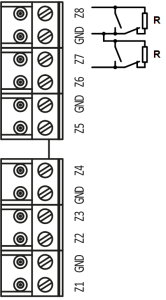
In programming, assign:
- Z7 – “Lockout A+B”
- Z8 – “Free Passage A+B”
“Lockout” can be assigned to access point A, access point B, or both (A+B).
“Free Passage” can be assigned to access point A, access point B, or both (A+B).
Zones with Lockout and Free Passage types operate on both short-circuit and open-circuit conditions.
Connecting Actuating Devices
Electric Locks
The availability of normally closed and normally open relay contacts, along with the ability to program the activation time of the lock over a wide range (from 1 to 255 seconds), allows the controller to operate electric locks and strikes of almost any type.
A special case is when the time is set to 0. In this case, a pulse of 200 ms is applied to the relay.
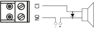
Example: One actuating device opens by applying voltage, while another opens by removing voltage.
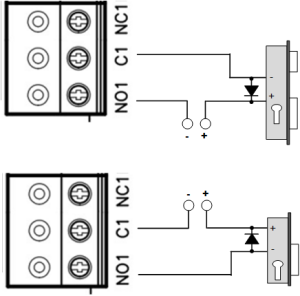
When using relay contacts to switch current through an inductive load (for example, when controlling an electromagnetic lock), high‑amplitude electrical impulses may occur. To prevent damage to the relay contacts, the inductive load must be shunted with a diode connected in reverse polarity across the coil’s power supply.
Note that inexpensive electromagnetic strikes do not allow prolonged voltage application. For such strikes, program the relay time so as not to overheat the strike coil.
For proper lock operation, the connected relay outputs must be assigned as lock outputs during programming.
Sirens and Bells
Electric bells, being inductive loads, require the use of a protection diode when connected to a DC source (see the warning about inductive loads above).
When connecting a siren, follow the siren’s user manual. The siren’s current draw must not exceed 1 A.
For non‑standard actuating devices (such as magnetic starters, turnstiles, etc.), please consult your equipment supplier regarding proper connection methods.
For proper siren operation during programming, assign the connected relay output as the siren (or alarm) output.
Connecting Ethernet
The Ethernet interface is used to network the system components (PC and controllers). The length of an Ethernet cable without additional equipment can be up to 100 meters, with data transmission speeds of up to 100 Mbps.
Direct Crimping – Connection to a Switch or Router:
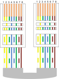
- White-yellow – white-yellow
- Yellow – yellow
- White-green – white-green
- Blue – blue
- White-blue – white-blue
- Green – green
- White-brown – white-brown
- Brown – brown
Crossover Wiring – Connection to a Computer:
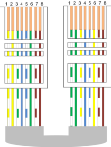
- White-yellow – white-green
- Yellow – green
- White-green – white-yellow
- Blue – blue
- White-blue – white-blue
- Green – yellow
- White-brown – white-brown
- Brown – brown
Factory Settings
Communicator
DHCP is enabled (the controller does not have a fixed IP address), and the ACS server addresses are not specified.
Inputs (Cables)
Z1 – Z8: Disabled
Outputs
Relays 1 – 4: Disabled
Readers
Wiegand 42bit
Warranty
The warranty period for U‑PROX devices (excluding power sources) is 2 years from the date of sale. If the device does not operate properly, please first contact support@u‑prox.systems; the issue may be resolved remotely.
Device supply, staff training, installation, commissioning, and warranty service for the U‑PROX IP400 controller are performed by the manufacturer or by organizations authorized by the manufacturer.
If commissioning is performed by an organization that is not authorized by the manufacturer, the consumer forfeits warranty service.
Warranty repairs will not be performed if the device fails due to:
- Improper connection,
- Non‑compliance with the operating instructions,
- Physical damage,
- Force majeure events.
Warranty and post‑warranty service for U‑PROX IP400 controllers is provided only by entities or organizations authorized by the manufacturer. The manufacturer reserves the right to make design changes that do not affect the main technical characteristics or reliability of the product.
U-PROX security system now with a camera
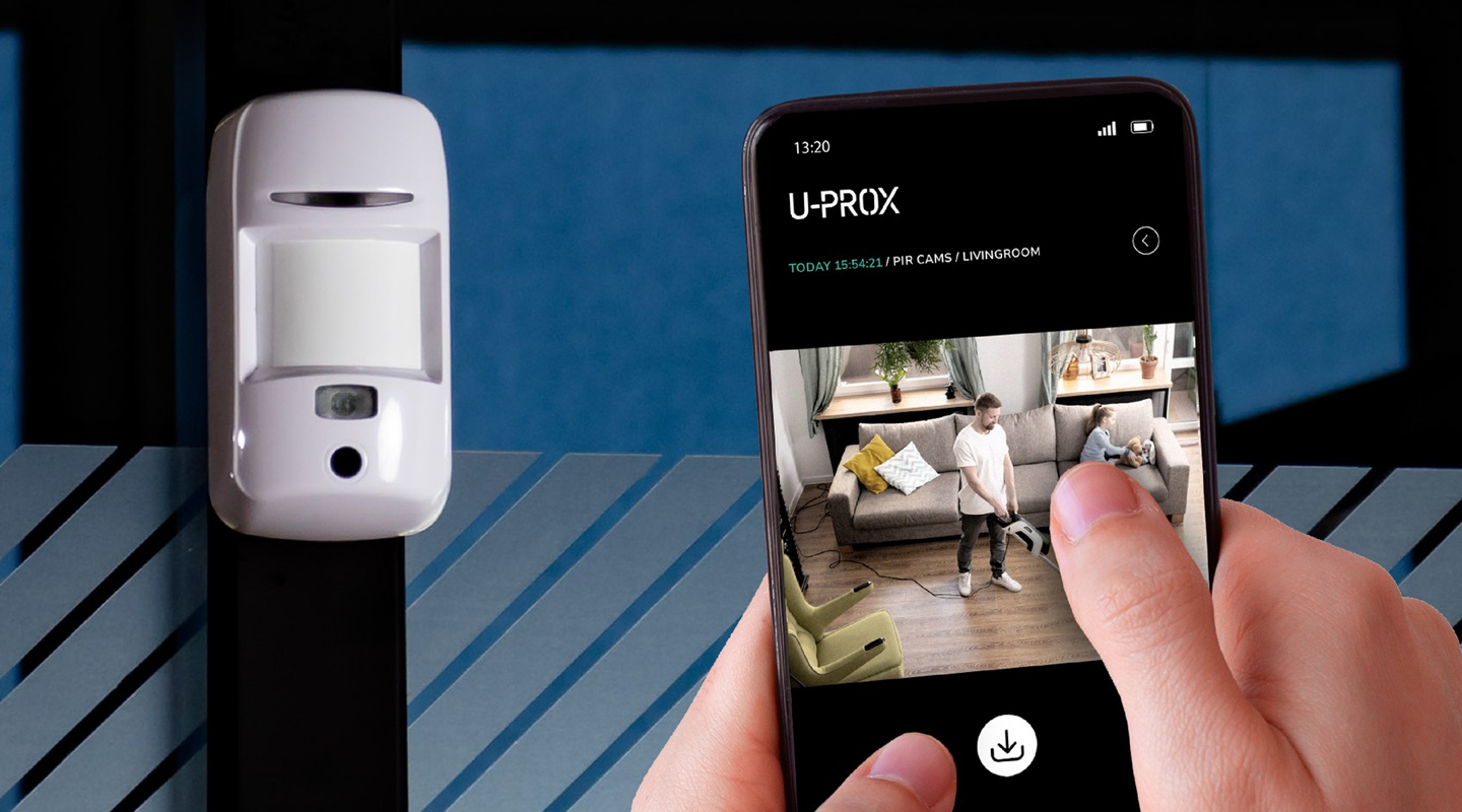
Meet the new product that is already available for order - the U-PROX PIR Cam wireless motion detector.
If the detector is triggered, it will send one or a series of photos to assess the situation to the U-PROX Home mobile app and the central monitoring station of the security company. The photo will be sent only during an obvious alarm.
This detector also has the “pet immune” function, which means that it is not sensitive to the movement of animals weighing up to 20 kg and up to 1 m high.
Simple installation, easy addition to the new generation U-PROX MPX security system hub, and an unrivaled communication range with the hub allow you to find a good location in your space.
Clear photo verification of the alarm has the highest quality specifications:
- motion detection range up to 12 m
- photo resolution: 640×480, 320×240, 240×176 pixels
- infrared illumination up to 8 meters for shooting in the dark and low light
- photo transfer time up to 9 seconds.
It should also be noted that U-PROX PIR Cam uses intelligent algorithms to eliminate false alarms. This allows you to be sure that you receive notifications only in case of a real threat.
Choose the new U-PROX PIR Cam with photo verification, because clarity adds peace of mind and comfort to life!
U-PROX SE readers now is OSDP Verified
We are very proud to announce our newest achievement - U-PROX SE series readers have successfully passed the SIA OSDP certification, confirming their reliability and security.
SIA (Security Industry Association) experts, recognized authorities in the field, have thoroughly tested and verified the compliance of U-PROX SE series readers with the standard and officially included them in the list of devices that have successfully passed OSDP v2.2 certification.
This is not just a certificate, it is a confirmation of the highest quality and unconditional compliance with the most stringent reliability and security standards in the access control industry.
What is OSDP? It is an advanced communication protocol that guarantees:
- maximum security: data is reliably protected from unauthorized access through encryption and device authentication.
- flawless operation: the access control system functions without failures, providing you with peace of mind and confidence.
- extended functionality: support for more functions than other protocols allows you to use U-PROX SE series readers in systems of any complexity and scale.
- easy integration: easy connection to OSDP-enabled controllers simplifies the process of installing and configuring your system.
From now on U-PROX SE Series readers are an investment in the future, a guarantee of reliable protection and uninterrupted operation of your next-generation access control system.
Завантаження
Quick start guide
CE Certification
Declaration of сonformity
Declaration of conformity RoHS
Latest firmware (white case)
Latest firmware (gray case)
Photos for online shops
Full manual
FAQ
-
You can buy U-Prox equipment from our partners.
-
Everything that is U-PROX, from the idea to the engineering implementation is done exclusively in Ukraine.
-
Yes, if the security system uses the U-PROX PIR Cam detector with photo fixation.
Thanks to it, users of the U-PROX Home mobile application can receive a photo from the detector at any time by pressing one button.
Also, when a photo is received on request, it is possible to save it to the user’s smartphone photo gallery and enlarge it if necessary.
The owner of the security system can also configure permissions to send photos in case of an alarm to security companies.
-
You can prevent water leaks in your apartment or house thanks to automation devices from U-PROX. The flood prevention system warns you of an unwanted water leak in the U-PROX Home app and automatically shuts off the water supply in case of a pipe burst or a malfunction of the washing machine.
The smart valve control and power supply device allows you to automatically shut off/open the water supply when arming/disarming the room.
You can also create personalized schedules for arming/disarming/operating the relay/water valve.
-
It is reliable communication that distinguishes the U-PROX security system from its competitors. We use DSTU GOST28147-89 encryption with reverse gamma, 256-bit key (3DES level).
Any of our radio devices operates in the notification (notification) mode, not polling, that is, as soon as an event occurs, it is immediately transmitted to U-PROX. In turn, the security center confirms the reception of the data packet by sending a response. The communication is two-way, imitation-resistant: the packet contains the detector serial number and the packet sequence number, which makes it impossible to replace the detector or send the same data packet by an intruder.The detector periodically sends data about its status to U-PROX, notifying that it is “alive”. We call this a “heartbeat”. In response, it receives confirmation and additional commands.
If the detector is installed in a place with poor conditions, it is used:
- increasing the radio communication power – 3 gradations of the transmitting device power are available,
- switching the data rate to improve the sensitivity of the receiving path,
- switching to other (backup) channels in the frequency range of 868.0 … 868.6 MHz.
In turn, the basic U-PROX device has 2 transceivers that work simultaneously to receive signals on different channels and speeds. And of course, there is a definition of radio jamming.
-
- We believe that this is our future – in 2-3 years, wireless equipment will occupy a large part of the security systems market. Almost everything will be wireless, and prices for such solutions will decrease.
- Wireless solutions are fast, convenient, and reliable.
- Will not spoil the interior design and renovation during installation, as it requires minimal installation work.
- Minimize the time spent on installing the security system.
- U-PROX WDC, U-PROX Wireport, U-PROX Multiplexer and U-PROX Siren have wired inputs to which wired devices can also be connected.
-
The sensors are powered by their own batteries.
And the U-PROX security center is equipped with a lithium-ion battery, which will provide autonomous power for 24 hours.
And if this is not enough, then you can use the design feature of U-PROX devices – an input power supply of 12V DC, which means that an external uninterruptible power supply can be used, or a car battery, then the autonomous life can be increased, even up to several weeks.
-
Your device communicates with the security company via two GPRS/LTE channels and the Internet – Wi-Fi or Ethernet.
If you try to “jam” or somehow block the communication channel, U-PROX will send a signal informing you.
-
If the animal is no more than 25 kg, then we will install special sensors that do not react to such animals, it is not required to restrict pets in movement.
If the animal is large, then we recommend allocating a space for it in the room, where sensors that react to movement will not be installed. There, you can install a sensor that responds to glass breakage, or sensors for opening doors and windows. -
Most of the sensors are powered by lithium batteries. They have sufficient capacity and operating temperature range.
Thanks to the adaptive power of the radio transmitters and the optimized data transmission protocol, the service life can be up to 7 years. The shortest service life of alkaline batteries “finger” or AAA, which are installed in the keyboard – up to 2 years.
But the replacement does not even require a screwdriver, the keyboard is removed using a regular plastic discount or bank card.
-
Modern systems work via an Internet connection, this is mobile Internet in LTE networks or fixed cable.
U-PROX uses both connections, thus providing data transmission redundancy to the monitoring station in case of blocking or jamming of GSM-communication or cable breakage.
Control of communication with the device is provided by the monitoring panel.
-
We use a proprietary technology called “U-PROX BAND”, it operates in the 868.0-868.6 MHz frequency range allocated for such systems and transmitter powers allowed without licensing up to 25 MW in the basic device, up to 20 mW in detectors, 10 mW in key fobs, with dynamic adjustment (the first exchange attempt is always at minimum power).
U-PROX BAND has significant advantages over its competitors: the length of the packets transmitted over the air is almost two times less, the optimized retry algorithm (energy consumption-wise), the sensitivity of the detector receivers is higher (this is the range both in line of sight and in building conditions). The U-PROX security center has two transceivers operating at different frequencies in the permitted range, providing redundant data transmission from sensors.
One of the “tricks” of U-PROX BAND is the function of updating the software of all elements over the air. If any shortcomings are corrected or the functionality of the device is added, then the owner and the security company do not need to worry about dismantling, sending for an update. The update will occur automatically after the automatic update of the basic device.
-
The security group is a logically independent unit in the security system.
It combines a group of sensors, which is placed and removed from protection separately and independently of others.
This can be done by a user who is authorized to manage a specific group.
-
This is a function that can work in any of the security groups.
It is implemented as follows. Consider the example of the house. When people put guards in this mode, the sensors that protect the perimeter: doors, windows, or even the entire first floor – become active. Other sensors – indoors – inactive. So, you can move freely inside the room, and intrusion from the outside will be detected.
-
You can install the U-PROX Security System even if you have no wired internet.
Since the backup communication source is the LTE/GSM network (the mobile operator card is installed).
But in this case, you lose one of the communication channels.
-
Wi-Fi is a wireless technology for connecting devices to the wired Internet.
It is implemented in all security centers (hubs).
The central unit in this case can be placed anywhere.
-
This is implemented using cloud technology.
With the security panel, the system works directly, “without intermediaries”.
With the user’s smartphone, the mediator is the cell of the device in the cloud, through which events are displayed on the smartphone and control commands from the user are passed.
-
If the phone is out of network, the security system remote control and watch events will not work.
But you can get an alarm notification if you set up a call from the device to the user’s phone. This mode is indispensable if the system operates autonomously, without remote monitoring.
We advise you to entrust security only to specialized companies, which will monitor your facility 24/7 and respond in case of alarm notification.
U-PROX is the best wireless device for remote protection.
-
Everything that is in U-PROX, from the idea to the engineering implementation is done exclusively in Ukraine.
-
- Modern energy-saving technologies allow you not to think about replacing batteries for several years (2-7 years).
- 2 weeks before the full discharge, the security system will warn you and the service security organization about the discharge.
- Popular battery sizes are used ААА, CR2, CR123A і CR2032.
-
The U-PROX security system has a refined design.
As standard, the cases of devices are executed either white or black.
For WDC sensors, the white starter kit includes replaceable dark brown housings.
-
The use of mobile applications U-PROX Home and U-PROX Installer allowed to separate system settings and management.
The U-PROX Home application is used to control the U-PROX security system. The application implements the required set of functions:
- Arming.
- Disarming.
- Arming in night mode.
- Alarm button.
- Event history with simple filters.
- View temperature from sensors.
- Add camcorders with zones.
- Watch the video from a connected camera.
- In the event of any failure in the system application, U-PROX brings this information to the home screen, and notify the user via Push message.
U-PROX Installer is used to configure the security system. Through an application is performed the primary activation of the sensors
-
PACS — Physical Access Control System —an access control and management system is a set of hardware and software control and management tools.
The main goal is to restrict and register the entry-exit of objects in a given area through “points of passage”: doors, gates, etc.
The main task is to control access to a given territory (who to let in, at what time and to what territory), including also:
- restricting access to a given territory;
- identification of a person who has access to a given territory.
-
Areas of application have a wide range of ACS:
- company offices, business centers;
- banks;
- educational institutions (schools, technical schools, universities);
- industrial enterprises;
- protected areas;
- parking lots;
- places of passage of vehicles;
- private houses;
- residential complexes;
- cottages;
- hotels;
- public institutions (sports complexes, museums, metro, etc.)
-
An identifier is the basic element of an access control system that stores a code.
Each client is assigned a specific key (code), which serves to determine the owner’s rights – identification.
A card, a key fob, a tag can perform the function of an identifier.
-
The control panes is the “brain” of the system, which determines whether or not the owner of the identifier is allowed to enter the door.
It has a built-in memory that stores identifier codes with a list of access rights for each of them.
When a person presents (brings to the reader) an identifier, the code read from it is compared with the one stored in the database, on the basis of which a decision is made to open the door.
-
A reader is a device that reads the code (key) of the identifier and transmits it to the controller.
-
Open formats JSON and SOAP (XML) allow interaction between different applications, exchange data with access control systems and create applications that complement and extend the standard functionality of the U-PROX Web system.
API capabilities:
- Secure data exchange over a computer network.
- WEB service – the opportunity to interact with any platform and programming environment for SOAP and JSON protocols.
- Implementation of the user interface using the API.
- The ability to integrate with other systems and applications implemented by third-party developers.
-
U-PROX WEB provides a full range of solutions for quick installation, configuration and daily use of IP ACS by enterprises of any size, from a small office to a large company with many branches.
U-PROX Web has a full-featured web interface with fine-tuning of all ACS capabilities and provides the ability to monitor events, configure equipment, manage personnel access, and generate reports.
-
You can buy U-Prox equipment from our partners.
-
- Connect wires D0 (green) and D1 (white) with each other
- Apply power to the reader
- Connect to the reader with application U-Prox Config installed on smartphone.
- Select “Settings”
- Set a password
- Go back
- Press “Save Settings”
- Press “Disconnect”
-
15 years ago massively used wired phones, mobile phones were either business or luxury. Now almost everyone has a mobile phone. It’s not only comfortable. The quality of wireless communication is steadily increasing.
The same situation with security systems. Wired systems require high-quality cable, trained personnel with electrical education, quality installation with line inspection, construction work with drilling, wiring, and other inconveniences. All this requires a lot of time.
As a result, we have a total cost that includes work. And compared with wireless systems, it is much higher. The wireless security system can be installed independently, the kit includes everything you need for installation.
The U-PROX security system has U-PROX BAND radio communication technology. It has unsurpassed characteristics in range, resistance to interference, due to channel redundancy, and is very efficient in terms of energy consumption.
-
It is very easy to install the U-PROX security system. Everything you need for installation: screws, fasteners, come complete with each sensor. The devices have simple mounts. Installation of the sensors to the required space can be done using screws or using two-way tape.
The overall security system installation will take about 10-15 minutes.It is very easy to install the U-PROX security system.
Everything you need for installation: screws, fasteners, come complete with each sensor. The devices have simple mounts.
Installation of the sensors to the required space can be done using screws or using two-way tape.
The overall security system installation will take about 10-15 minutes.