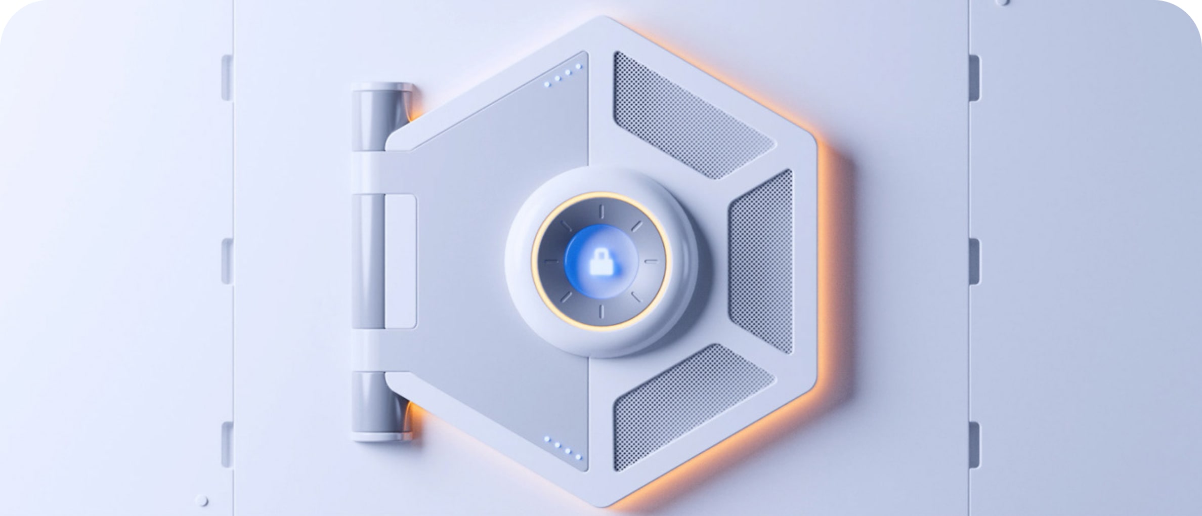
U-PROX IP401
Cloud-based access control panel
10K
identifiers
BLE
for configuration

Сontrol panel for one door
REX
touch button
WiFi
network (2.4 GHz)
Ergonomic case

OSDP reader support

Programming via smartphone

Cloud-based access control panel
Access control panel for one door with Wi-Fi
Powerful control panel with Wi-Fi
- Controller in a small case
- Wi-Fi IEEE802.11 b/g/n, 2.4 GHz
- Supports DHCP, DNS, works through NAT
- 10,000 cards and 20,000 events
- Designed for maximum autonomy


Single-sided door control panel
- One single-sided door
- Built-in RTE (REX) touch button
- DC, RTE (REX) inputs
- Solid state relay for the lock control
- Alarm output
Works with the cloud ACS
- Working with U-PROX ACS Cloud
- Firmware update from the cloud
- Configuration via smartphone (Wi-Fi, IP addresses, etc.)
- Supports U-PROX IP/WEB

Gallery
Photos and videos


NEW PRODUCTS


Want to buy?
Contact partner companies to purchase or install security and automation devices.
Want to sell?
Become an official distributor, reseller or installer of U-PROX security and safety systems.
TECHNICAL SPECIFICATIONS
| Inputs |
DC - Door Contact RTE - Request to Exit button Built-in RTE touch button |
|---|---|
| Outputs (Relays) |
NO, COM - solid state relay, 1 A @ 30 V (inversion relay mode) OUT - alarm output, OC 0.16 A @ 12 V |
| Reader |
OSDP: one reader , up to 1200 m RS232: one reader U-PROX SE/SL, up to 10 m |
| Connection | 2.4 GHz, 802.11b/g/n, Open/WPA/WPA2/WEP |
| Memory |
10 000 user ID’s 20 000 events, weekly schedules - 250, time zones - 250, holidays - 250 |
| Power | +10,8...+15 V, consumption < 100 mA @12V |
| Dimensions | 84.3 х 84.3 х 14.5 mm |
| Weight | 0.18 kg |
| Case colour | black |
| Case material | ABS+PC plastic, Gorilla Glass |
| Operating temperature range | from -10°C to +55°C |
| Configuration | With the U-PROX Config mobile app via Bluetooth |
| Complete set |
1. U-PROX IP401; 2. Mounting kit; 3. Quick start guide |
Color


+4
U-PROX IP401 User manual
Description
U-PROX IP401 is a cloud-based controller designed for use in access control systems (ACS) ofvarious scales — from small office facilities to large enterprises. The controller provides accesscontrol for residential and industrial premises and supports event logging and time-and-attendancetracking.
The controller is supplied in an enclosure with a built-in capacitive “Request to Exit” button andwithout a power supply unit.
U-PROX IP401 operates with readers connected:
- via the RS-232 interface (U-PROX readers only);
- via the RS-485 interface using the OSDP protocol (U-PROX SE series readers or third-partyreaders supporting OSDP 2.2).
The controller processes data received from the reader and controls actuators, such as electric locks orsirens, using two outputs.
The device is equipped with two fixed-function inputs: one for connecting a door status sensor andone for the request-to-exit button.
The controller can operate in standalone mode or as part of a networked access control system. Controllers are interconnected via the Wi-Fi interface (wireless computer network).
Network configuration is performed via Bluetooth Low Energy (BLE) using the U-PROX Configmobile application.
Controller firmware updates are performed remotely via Wi-Fi.
The controller is powered by 12 V DC.
U-PROX IP401 is designed to control a single door, equipped with one reader and a request-to-exitbutton. A large non-volatile memory capacity allows the controller to manage access for up to 10,000 identifiers.
Carefully engineered technical and mechanical design, Wi-Fi connectivity, non-volatile memory, a real-time clock, and protection of reader ports against short circuits, overvoltage, and reverse polaritymake U-PROX IP401 a versatile solution for building modern access control systems.
Technical Specifications
Power supply: external 12V source; current consumption (with no load) — no more than 100 mA; ripple amplitude — no more than 500 mV.
Reader connection:
- RS232 – up to 10 m (contactless U-PROX identifiers)
- RS485 (OSDP2.2) – up to 1000 m
Built-in touch button: request for exit function.
Inputs: door contact (DC) and request to exit button (RTE).
Tamper contact: for enclosure opening detection.
Outputs: one solid state relay (NO/NC, COM) — 1 A @ 30 V; alarm output (open collector) — 12V @ 160 mA.
Wireless interface: Wi-Fi 2.4 GHz, 802.11b/g/n, supports Open/WPA/WPA2/WEP.
Cloud ACS operation: U-PROX ACS Cloud.
Local ACS operation: U-PROX WEB.
Configuration: full configuration is performed via ACS software through a computer network.
Real-time clock.
Non-volatile memory:
- Identifiers — 10,000
- Events — 20,000
- Time zones — 250
- Weekly schedules — 250
- Holidays — 250
- Temporary identifiers — 1,000
Terms
Identifiers: In access control systems, each user has a unique code. It can be plastic cards, key fobs, etc.
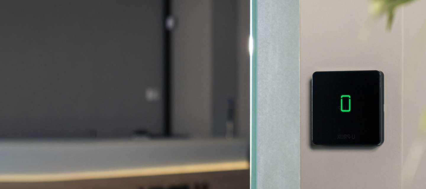
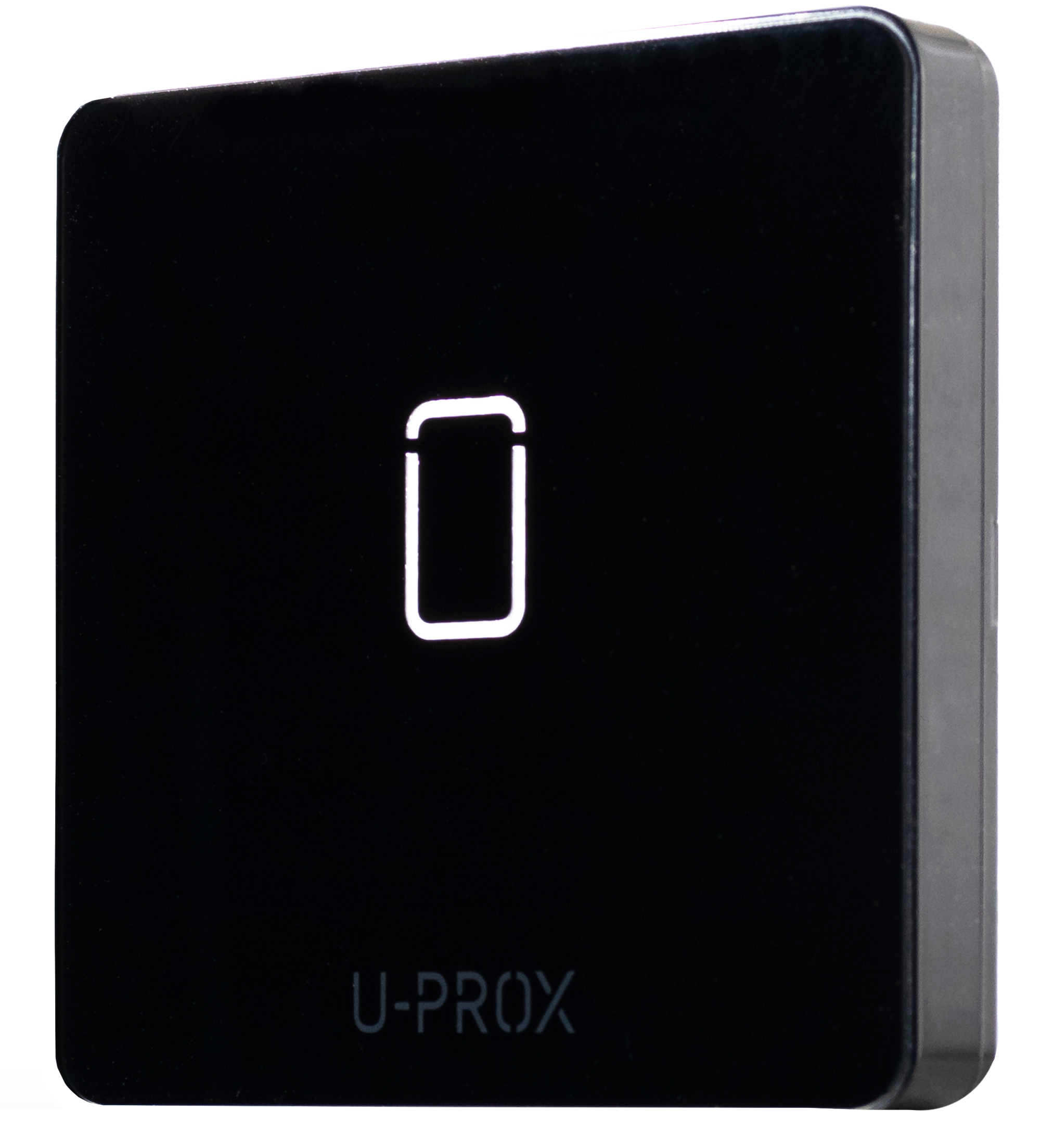
Reader: Devices that read codes and connect to the ACS control panel. The Wiegand RS232 or OSDP interfaces are used.
PIN code: A code entered with the reader keypad; may function independently or as an addition to a card or key fob.
Door: An access control point (e.g., door, turnstile). Access point — a logical unit of the system.
Access point: See “Door.”
Passage point: A logical ACS unit that controls passage through a door in one direction; includes a reader, control panel (or its part), and actuator. A single-point door is one-way; two-point — two-way.
Exit request button: Used to exit a room.
Door contact: An input for connecting magnetic, rotary, or other sensors to monitor door state.
“Passage time” interval: The time after a user passes during which the door is not monitored even if the contact is triggered.
Identifier attempt detection: If several unregistered identifiers are presented consecutively, the control panel switches to alarm mode.
Schedules: Time intervals and schedules that define access rights. The control panel can store up to 250 time intervals, 250 weekly schedules, and 250 holidays.
Time zones: Time intervals used for organizing access schedules.
Download: The process of transferring configuration data from a computer to the control panel after programming.
Description and Operation
Control panel Structure
The device is shown in Fig. 1.

The control panel consists of the following components:
- Upper part of the device case
- Request to exit touch button
- Bottom part of the case
- Mounting screw
- Device board with terminal blocks
Fig. 1. Appearance of the U-PROX IP401
Terminal Block Layout
The layout of the connectors on the bottom board of the device is shown in Fig. 2.

Control panel Terminal Functions
| Terminal | Label | Description |
|---|---|---|
| GND | – | External power supply connection V- |
| +12V | – | External power supply connection V- |
| NO/NC |
Normal open/Normal closed
|
Relay contacts |
| COM | Common |
Relay contacts
|
| RED | +12V |
Reader
V+
|
| BLK | GND |
Reader
V-
|
| GRN | Data 0 |
Reader Data 0
|
| WHT | Data 1 |
Reader Data 1
|
| GND |
Ground
|
Ground |
| DC | Door contact | – |
| RTE | Exit request button | – |
| OUT | Alarm output | – |
Control panel Indication
Access mode indication is performed by the reader connected to the control panel. Default settings are as follows:
- Standby mode: no sound, red flashing once per second
- Night mode or Lock: no sound, red-yellow flashing once per second
- Alarm: no sound, solid red
- Card registration: no sound, green flashing once per second
- Initialization: no sound, no light indication
- Data read/upload, firmware update: no sound, solid red
- Access granted: short beep, steady green; 5 seconds before door timeout — short beep once per second
- Access denied: continuous sound, solid red
The touch button LED indicates button pressing only!
Control panel Operation
Control panels are supplied in an unloaded (factory) state, in which the red LED flashes once per second.
To operate, the control panel must be configured using setup software on a mobile device. After the configuration is uploaded and all connections are correct, the control panel switches to “Standby” mode.
The control panel can manage one passage point that operates in four modes: “Standby”, “Alarm”, “Block”, and “Free Passage”. The “Free Passage” mode has the highest priority (e.g., firealarm), followed by “Block”, “Alarm”, and “Standby”.
Control panel Programming
Connect to the control panel using U-PROX Config software via Bluetooth Low Energy (BLE). Supported devices: Android 5.0+ and iOS 8.0+ with Bluetooth 4.0+ (BLE).
- Launch U-PROX Config:
Launch U-PROX Config on your mobile device. If Bluetooth is disabled, enable it (for Android 6.0 and higher — enable location services). Tap “Search” to detect nearby devices.

- Connect to the control panel:
Select the U-PROX IP401 control panel from the list and press “Connect.”
- Enter the engineering code:
After selecting the device, you’ll be prompted to enter an engineering code. Enter the default code (1234) or another code provided by the manufacturer.
- Configure network parameters:
Using U-PROX Config, configure Wi-Fi, DNS, IP address (or enable DHCP), and the port used to connect to the ACS server or cloud system.
Default code — 1234
- Add the control panel to access control system (ACS) according the ACS manual
- Register identifiers and create users:
Using the access control system (ACS), add identifiers (contactless cards, PIN codes, mobile identifiers) and assign appropriate access rights and schedules.
- Upload configuration:
After completing all settings upload the configuration to the control panel. The device will switch to standby mode.

Control panel Firmware Update
After connecting to Wi-Fi, the “Firmware Update” option will appear in the control panel’s settings menu. Tap this option, choose the update type (from the default server or via a custom link), and the firmware will download in the background. The control panel will update automatically (the process takes approximately 5 minutes).
Maintenance
Factory Reset
- Disconnect power from the control panel
- Remove the upper cover of the control panel
- Short the OUT and DC contacts
- Place the upper cover back
- Apply power and wait until the beep ends (about 40 seconds)
- Power off the control panel, remove the cover, and remove the OUT and DC contacts
Engineer Password Reset
- Disconnect power from the control panel
- Remove the upper cover of the control panel
- Short the OUT and RTE contacts
- Replace the upper cover
- Apply power and wait for 40 seconds
- Power off the control panel, remove the cover, and break apart the OUT and RTE contacts
Factory Settings
- Communicator: Wi-Fi — not configured, DHCP enabled, cloud ACS server address: acs-panels.u-prox.systems
- Inputs (loops): DC — door contact; RTE — exit request button
- Outputs: Relay — lock mode (inversion disabled), OUT — “Alarm”
- Reader: OSDP
Warranty
The manufacturer guarantees that the U-PROX IP401 control panel complies with the parameters described in this manual when properly stored and operated.
- Storage warranty period — 6 months from the date of manufacture
- Operational warranty period — 24 months from the date of commissioning
- Delivery, personnel training, installation, commissioning, and warranty service are carried out by the manufacturer or authorized organizations
- In case of a defect caused by the manufacturer, correction is performed within 10 days
- Warranty service is not provided in cases of:
- Incorrect connection,
- Failure to follow this manual,
- Mechanical damage,
- Natural disasters.
- The manufacturer reserves the right to make design modifications that do not affect key specifications or reliability.
Training and Technical Support
Training courses covering installation and usage of the U-PROX IP401 control panel are conducted by “Limited Liability Company Integrated Technical Vision.” For additional information, please contact the company’s staff at the phone numbers listed below.
Technical support:
+38 (091) 481 01 69
support@u-prox.systems
https://t.me/u_prox_support_bot
This support is intended for trained specialists. End users should contact their dealers or installers before reaching out to “Limited Liability Company Integrated Technical Vision.”
Technical information is available at: www.u-prox.systems
Certification
“Limited Liability Company Integrated Technical Vision” declares that U-PROX IP401 complies with the Electromagnetic Compatibility Directive 2014/30/EU and Directive 2011/65/EU (RoHS). The original Declaration of Conformity is available at www.u-prox.systems in the “Certificates” section.
www.u-prox.systems
U-PROX IP401 Cloud Access Control panel
U-PROX security system now with a camera
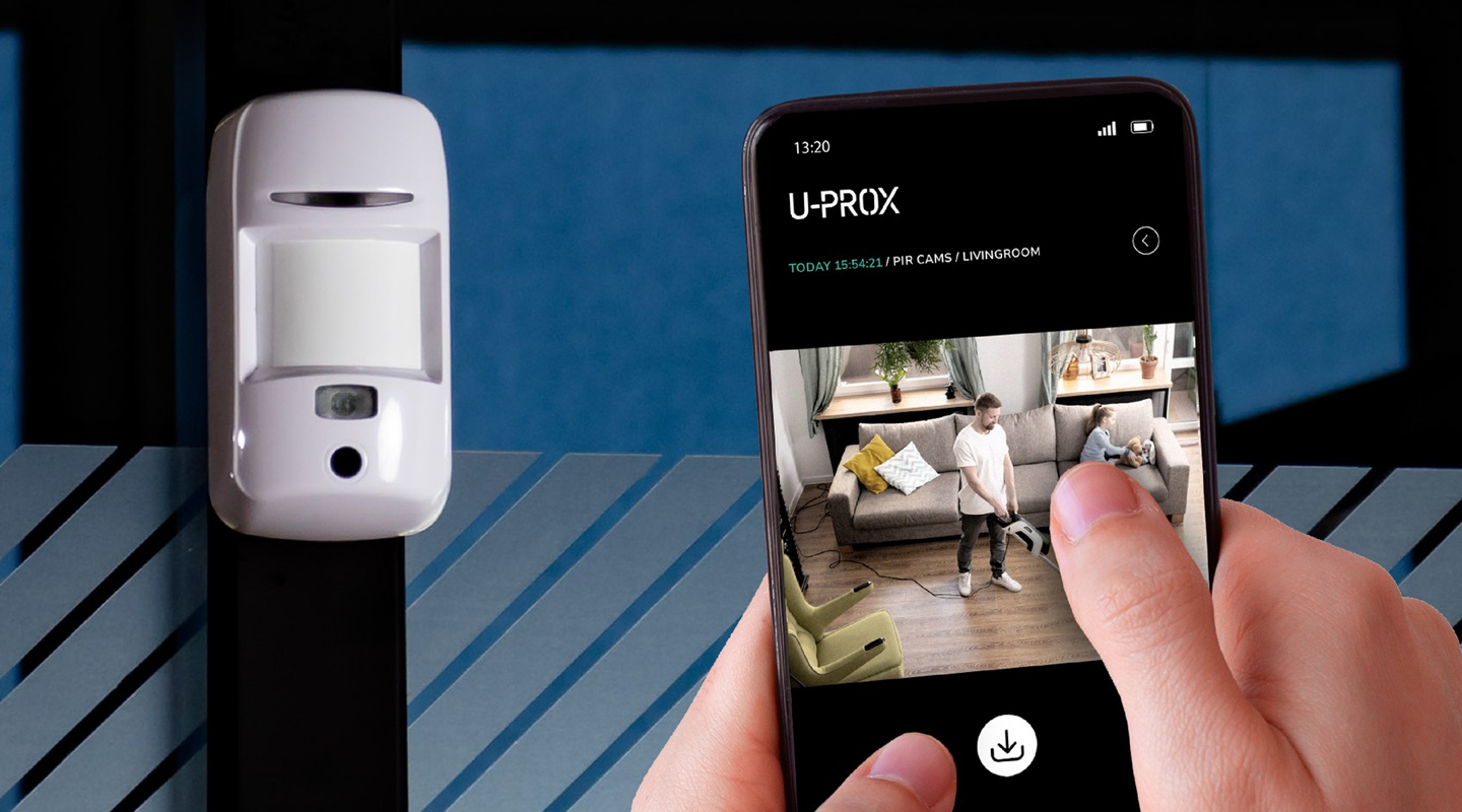
Meet the new product that is already available for order - the U-PROX PIR Cam wireless motion detector.
If the detector is triggered, it will send one or a series of photos to assess the situation to the U-PROX Home mobile app and the central monitoring station of the security company. The photo will be sent only during an obvious alarm.
This detector also has the “pet immune” function, which means that it is not sensitive to the movement of animals weighing up to 20 kg and up to 1 m high.
Simple installation, easy addition to the new generation U-PROX MPX security system hub, and an unrivaled communication range with the hub allow you to find a good location in your space.
Clear photo verification of the alarm has the highest quality specifications:
- motion detection range up to 12 m
- photo resolution: 640×480, 320×240, 240×176 pixels
- infrared illumination up to 8 meters for shooting in the dark and low light
- photo transfer time up to 9 seconds.
It should also be noted that U-PROX PIR Cam uses intelligent algorithms to eliminate false alarms. This allows you to be sure that you receive notifications only in case of a real threat.
Choose the new U-PROX PIR Cam with photo verification, because clarity adds peace of mind and comfort to life!
U-PROX SE readers now is OSDP Verified
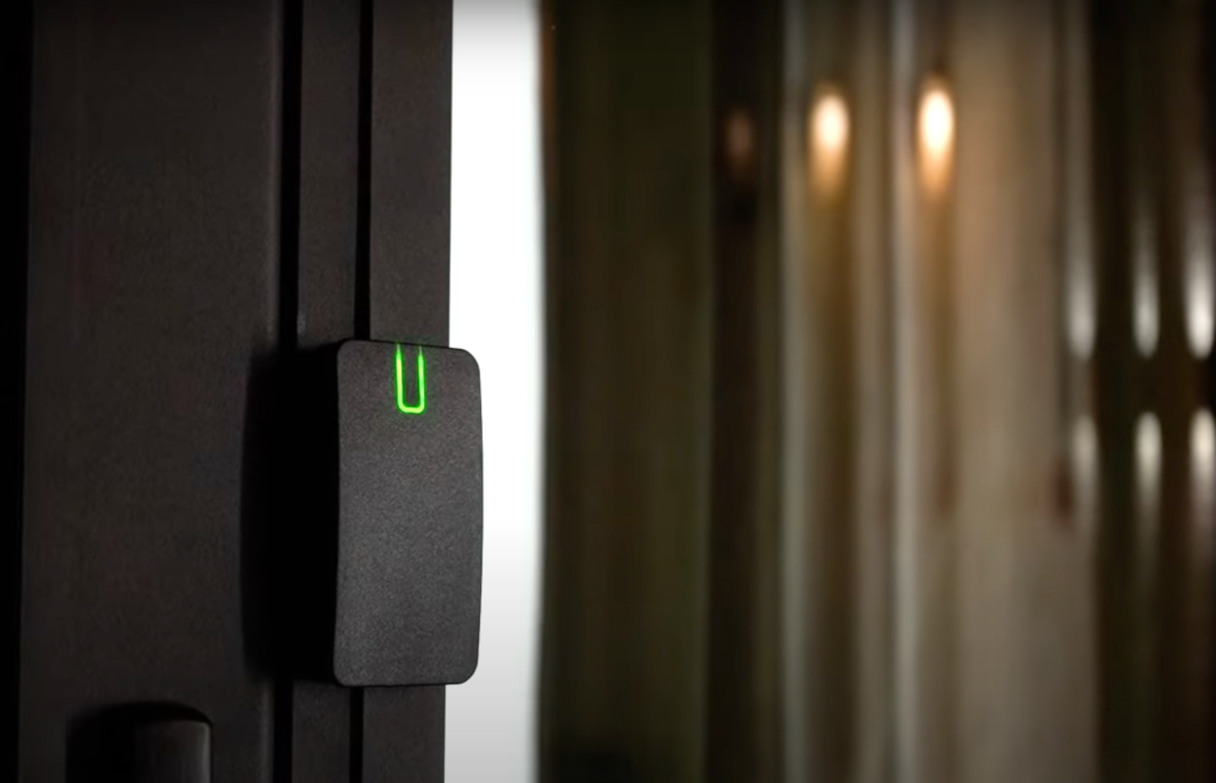
We are very proud to announce our newest achievement - U-PROX SE series readers have successfully passed the SIA OSDP certification, confirming their reliability and security.
SIA (Security Industry Association) experts, recognized authorities in the field, have thoroughly tested and verified the compliance of U-PROX SE series readers with the standard and officially included them in the list of devices that have successfully passed OSDP v2.2 certification.
This is not just a certificate, it is a confirmation of the highest quality and unconditional compliance with the most stringent reliability and security standards in the access control industry.
What is OSDP? It is an advanced communication protocol that guarantees:
- maximum security: data is reliably protected from unauthorized access through encryption and device authentication.
- flawless operation: the access control system functions without failures, providing you with peace of mind and confidence.
- extended functionality: support for more functions than other protocols allows you to use U-PROX SE series readers in systems of any complexity and scale.
- easy integration: easy connection to OSDP-enabled controllers simplifies the process of installing and configuring your system.
From now on U-PROX SE Series readers are an investment in the future, a guarantee of reliable protection and uninterrupted operation of your next-generation access control system.
Downloads
FAQ
-
- Connect wires D0 (green) and D1 (white) with each other
- Apply power to the reader
- Connect to the reader with application U-Prox Config installed on smartphone.
- Select “Settings”
- Set a password
- Go back
- Press “Save Settings”
- Press “Disconnect”
-
The control panes is the “brain” of the system, which determines whether or not the owner of the identifier is allowed to enter the door.
It has a built-in memory that stores identifier codes with a list of access rights for each of them.
When a person presents (brings to the reader) an identifier, the code read from it is compared with the one stored in the database, on the basis of which a decision is made to open the door.
-
A reader is a device that reads the code (key) of the identifier and transmits it to the controller.
-
PACS — Physical Access Control System —an access control and management system is a set of hardware and software control and management tools.
The main goal is to restrict and register the entry-exit of objects in a given area through “points of passage”: doors, gates, etc.
The main task is to control access to a given territory (who to let in, at what time and to what territory), including also:
- restricting access to a given territory;
- identification of a person who has access to a given territory.
-
An identifier is the basic element of an access control system that stores a code.
Each client is assigned a specific key (code), which serves to determine the owner’s rights – identification.
A card, a key fob, a tag can perform the function of an identifier.
-
Areas of application have a wide range of ACS:
- company offices, business centers;
- banks;
- educational institutions (schools, technical schools, universities);
- industrial enterprises;
- protected areas;
- parking lots;
- places of passage of vehicles;
- private houses;
- residential complexes;
- cottages;
- hotels;
- public institutions (sports complexes, museums, metro, etc.)
-
Everything that is U-PROX, from the idea to the engineering implementation is done exclusively in Ukraine.
-
You can buy U-Prox equipment from our partners.
-
Open formats JSON and SOAP (XML) allow interaction between different applications, exchange data with access control systems and create applications that complement and extend the standard functionality of the U-PROX Web system.
API capabilities:
- Secure data exchange over a computer network.
- WEB service – the opportunity to interact with any platform and programming environment for SOAP and JSON protocols.
- Implementation of the user interface using the API.
- The ability to integrate with other systems and applications implemented by third-party developers.
-
U-PROX WEB provides a full range of solutions for quick installation, configuration and daily use of IP ACS by enterprises of any size, from a small office to a large company with many branches.
U-PROX Web has a full-featured web interface with fine-tuning of all ACS capabilities and provides the ability to monitor events, configure equipment, manage personnel access, and generate reports.