U-PROX RM
Relay module for elevator control panel


Remote control

Controling of access to floors

Executive modules
Access control to building floors
The relay module
- 8 relays (C NO NC)
- 8 inputs for monitoring and remote control
- EMG input for emergency unlocking


Easy installation
- Mounting in the gap of elevator buttons loops
- Connection to the elevator executive modules
- RS485 connection to U-PROX IC E
Emergency handling
Deactivation of the elevator controller in case of emergency:
- Failure of the U-PROX IC E
- Failure of U-PROX RM modules
- Breakage of the “Emergency” loop of U-PROX RM
- At the operator’s command from the ACS

NEW PRODUCTS


Want to buy?
Contact partner companies to purchase or install security and automation devices.
Want to sell?
Become an official distributor, reseller or installer of U-PROX security and safety systems.
TECHNICAL CHARACTERISTICS
| Floors | up to 8 for one module |
|---|---|
| Outputs (Relays) | 8 (NO, NC, COM), 5 А @ 24 В |
| Inputs | 8 inputs (EOL resistor - 2 kOm) |
| RS485 port |
up to 1000 m, connecting to U-PROX IC E |
| Power | +10.8...+15 V (DC), consumption < 400 mA @12V |
| Dimensions | 112 х 88 х 20 mm |
| Weight | 0.3 kg |
| Operating temperature range | from 0oC to +55oC |
| Complete set |
1. U-PROX RM; 2. Installation kit; 3. Quick guide; |
Color


U-PROX RM User manual
Relay Expansion Module
U‑PROX RM
Installation and Operation Manual
Rights and Their Protection
All rights to this document are owned by Limited Liability Company Integrated Technical Vision.
Trademarks
ITV® and U‑PROX® are registered trademarks of Limited Liability Company Integrated Technical Vision.
About This Document
This operating manual describes the procedure for installing, connecting, and operating the U‑PROX RM relay expansion module for the elevator controller of the U‑PROX IC E access control system. Before mounting the module, carefully read this manual.
The module’s characteristics and parameters are described in the Specifications section. The Terms section explains the terminology used in this document.
The external appearance of the relay module, as well as a description of its contacts and operating modes, is provided in the Description and Operation section. The installation and configuration procedure is described in the Operating Procedure with the Device section.
Attention! Before installing and connecting the device, study this manual carefully. Installation and connection of the module are permitted only by persons or organizations authorized by the manufacturer.
Training and Technical Support
Training courses covering installation and use of access control equipment are conducted by Limited Liability Company Integrated Technical Vision. For more information, contact the company at the phone number and e‑mail below.
Phone: +38 (091) 481‑01‑69
E‑mail: support@u-prox.systems
Telegram: https://t.me/u_prox_support_bot
This support is aimed at trained specialists. End users of Limited Liability Company Integrated Technical Vision products should contact their dealers or installers before contacting the manufacturer directly.
Technical information is available on the website: www.u-prox.systems
Certification
Limited Liability Company Integrated Technical Vision certifies that U‑PROX RM complies with the Electromagnetic Compatibility Directive 2014/30/EU and the RoHS Directive 2011/65/EU. The original Declaration of Conformity is available on the website under the Certificates section.
Contents
- Device Description
- Purpose of the Device
- Specifications
- Terms
- Description and Operation
- Controller Device (Overview)
- Function of the Module’s Contacts and Jumpers
- LED Indication of the Module
- Module Operation
- “Normal” Mode
- Remote Floor Access Provision
- Emergency Unlocking of the Elevator Control Panel
- Operating Procedure with the Device
- Connection Procedure
- Connecting Expansion Modules via the RS‑485 Bus
- Service and Maintenance
- Warranty Obligations
Device Description
The U‑PROX RM relay expansion modules are the executing devices in an elevator access control system based on the U‑PROX IC E controller, which is designed to control access to building floors. For identification purposes, U‑PROX WRS485 modules with connected Wiegand readers or U‑PROX SE series readers are used.
The U‑PROX IC E controller processes information received from the readers and from the inputs of the U‑PROX RM module, and it activates the permitted relays on the module to control the signaling lines on the elevator floor panel.
Purpose of the Device
The U‑PROX RM module is intended to expand the number of relays and outputs available for access control system controllers, particularly for the elevator controller U‑PROX IC E.
Specifications
Power Supply: External 12V source
Current Consumption: Not more than 400 mA from the 12V source
DC Ripple: Not more than 500 mV
RS‑485 Port: For connection to U‑PROX IC E
Inputs: 8 inputs for connecting cables with current monitoring (termination resistor – 2.2 kΩ)
Relays: 8 relays (NO, NC, COM contacts) rated at 5 A @ 30 V
Alarm Input: EMGR
Case Open Sensor Input: TMP
Terms
Identifiers: In access control systems, each user has an identifier with a unique code. Identifiers may be in the form of a plastic card, key fob, etc.
Reader: A device used to read identifier codes, connected to the ACS controller.
PIN Code: If readers have an integrated keypad, the PIN code entered on the keypad may serve as an identifier or as a supplement to a card or key fob. After a card is presented, the reader waits for the PIN code input.
Door: The access point where access is directly controlled (e.g., door, turnstile, access portal equipped with necessary control devices).
Access Point: See Door.
Passage Time Interval: When a door contact is broken, the access point enters “Alarm” mode; however, an alarm is not triggered if the contact is broken during the predetermined passage time interval. The interval starts when access is granted and ends when the door contact is broken and then restored.
Attempt to Guess an Identifier: The controller features a function that triggers alarm mode if an unregistered identifier is presented repeatedly. A correct presentation resets the counter. This function can be enabled and the number of allowed attempts specified during programming.
Schedules: When configuring user access rights, time and date intervals during which access is permitted are specified. Depending on the module version, up to 250 time intervals and 250 weekly schedules can be stored. Additionally, up to 250 annual holiday dates may be configured.
Time Zones: A time zone is a component of a schedule that organizes time intervals and associates them with access rights. They are used for verifying access permissions and user authorization, as well as for other functions based on schedules.
Loading: After programming the controller parameters, the configuration must be loaded (transferred from the computer to the controller).
Description and Operation
Module Device
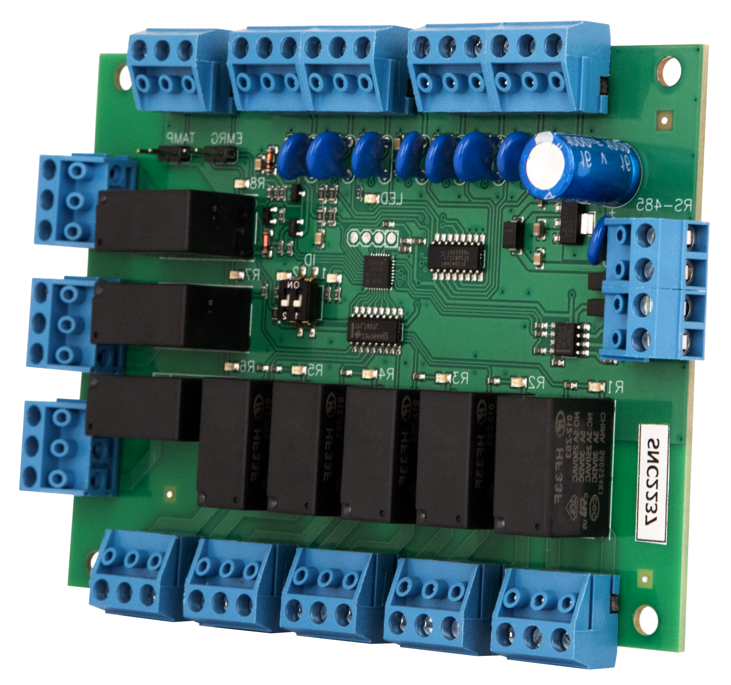
The external appearance of the U‑PROX RM relay module is shown in Figure 1.
Figure 1. External Appearance of U‑PROX RM
The layout of the module’s printed circuit board (including jumpers, buttons, and connectors) is shown in Figure 2.
Figure 2. PCB Layout of the Module
Function of the Module’s Contacts and Jumpers
| Contact | Name | Function |
|---|---|---|
| Z1…Z8 | Inputs | Zones 1–8 for cable connection and common ground |
| NC1 | Relay 1 | Normally closed contact |
| NO1 | Relay 1 | Normally open contact |
| C1 | Relay 1 | Common contact |
| A+ | RS‑485 | RS‑485 bus positive (A+) |
| B‑ | RS‑485 | RS‑485 bus negative (B‑) |
| GND | RS‑485 | RS‑485 ground |
| E+ | +12V | Power contact (+12V) |
| EMR | EMRG | Alarm input |
| TMP | Tamper | Case open sensor contact |
LED Indication of the Module
The module’s relay indicator LEDs (R1…R8) reflect the activation or deactivation of the corresponding relays. An LED lights up when its associated relay is energized.
Module Operation
“Normal” Mode: The module is connected to the U‑PROX IC E controller via the RS‑485 bus. The U‑PROX RM relays are connected to the elevator floor selection button circuits. In the de‑energized state, the module allows the buttons to function normally. Feedback cables may be connected to inputs Z1–Z8 from the elevator automation to detect when a floor button is pressed. When such feedback is present, a message “Floor Access Granted” is generated after a button is pressed.
Remote Floor Access Provision
Remote control cables can be connected to inputs Z1–Z8 to provide remote access control (for example, from a security post). When a floor button is pressed at the security post, a message “Floor Opened by Button” is generated.
Emergency Unlocking of the Elevator Control Panel
The U‑PROX RM relay module enters “Alarm – Emergency Unlock” mode if the connection with the U‑PROX IC E controller is lost or if the EMRG input is triggered. Each module is equipped with an EMRG input; in normal operation, the cable connected to this input is short‑circuited to ground. If the EMRG cable is broken or communication with the controller is lost, the elevator control module is de‑energized and full access to the floor selection panel is restored, allowing a user to select any floor without presenting an identifier.
Figure 5. Connection Diagram
Operating Procedure with the Module
The relay module is provided as a printed circuit board.
Figure 3. Overall Dimensions
Connection Procedure:
- Run the RS‑485 cable, the floor button control cables, and the remote control cables.
- Route the mounting cables.
- Set the module’s address using the DIP switches.
- Mount and secure the module.
- Connect the module to the elevator controller via the ACS software (follow the ACS instructions) and load the full configuration.
After these steps, the module is ready for operation.
Installation Recommendations
The module should be installed in a location that is accessible for maintenance.
Figure 4. Mounting Hole Marking
To install the module on a wall (see Figure 4):
- Open the housing cover, remove the board, align it to the desired mounting location, and mark the drill holes.
- Run the cables through the holes in the housing wall.
- Secure the module’s housing to the wall.
- Connect all necessary cables.
Connecting Expansion Modules via the RS‑485 Bus
The RS‑485 interface is used to connect expansion modules to the U‑PROX IC E controller. The RS‑485 bus can extend up to 1200 meters without additional equipment. When connecting devices on the RS‑485 bus, enable termination on the first and last devices by setting the termination jumpers (see Figure 5).
When connecting expansion modules:
- U‑PROX RM modules cannot be connected at the ends of the RS‑485 bus because they lack termination jumpers.
- The IDs of the U‑PROX RM modules must not be identical. Set a unique ID for each module using the DIP switches (from 0 to 7).
Figure 5. Connection of the Controller and Expansion Modules to the Data Bus
Service and Maintenance
Warranty and Post‑Warranty Service
Warranty and post‑warranty service for the U‑PROX RM relay module is provided only by persons or organizations authorized by the manufacturer.
Warranty Obligations
The manufacturer guarantees that the U‑PROX RM relay module conforms to the parameters described in this manual, provided that the storage and operating conditions specified herein are met.
Storage Warranty: 6 months from the date of manufacture.
Operational Warranty: 12 months from the date the device is put into operation.
Device supply, personnel training, installation, commissioning, and warranty service for the U‑PROX RM module are provided by the manufacturer or by authorized organizations.
If a defect due to the manufacturer is detected, the authorized organization will remedy it within 10 days of notification.
If commissioning is performed by an organization not authorized by the manufacturer, the consumer forfeits warranty service.
Warranty repairs will not be performed if the device fails due to improper connection, failure to comply with this manual, mechanical damage, or force majeure.
The manufacturer reserves the right to make design changes that do not affect the main technical characteristics or reliability of the device.
© 2024 Limited Liability Company Integrated Technical Vision
www.u-prox.systems
U-PROX security system now with a camera
Meet the new product that is already available for order - the U-PROX PIR Cam wireless motion detector.
If the detector is triggered, it will send one or a series of photos to assess the situation to the U-PROX Home mobile app and the central monitoring station of the security company. The photo will be sent only during an obvious alarm.
This detector also has the “pet immune” function, which means that it is not sensitive to the movement of animals weighing up to 20 kg and up to 1 m high.
Simple installation, easy addition to the new generation U-PROX MPX security system hub, and an unrivaled communication range with the hub allow you to find a good location in your space.
Clear photo verification of the alarm has the highest quality specifications:
- motion detection range up to 12 m
- photo resolution: 640×480, 320×240, 240×176 pixels
- infrared illumination up to 8 meters for shooting in the dark and low light
- photo transfer time up to 9 seconds.
It should also be noted that U-PROX PIR Cam uses intelligent algorithms to eliminate false alarms. This allows you to be sure that you receive notifications only in case of a real threat.
Choose the new U-PROX PIR Cam with photo verification, because clarity adds peace of mind and comfort to life!
U-PROX SE readers now is OSDP Verified
We are very proud to announce our newest achievement - U-PROX SE series readers have successfully passed the SIA OSDP certification, confirming their reliability and security.
SIA (Security Industry Association) experts, recognized authorities in the field, have thoroughly tested and verified the compliance of U-PROX SE series readers with the standard and officially included them in the list of devices that have successfully passed OSDP v2.2 certification.
This is not just a certificate, it is a confirmation of the highest quality and unconditional compliance with the most stringent reliability and security standards in the access control industry.
What is OSDP? It is an advanced communication protocol that guarantees:
- maximum security: data is reliably protected from unauthorized access through encryption and device authentication.
- flawless operation: the access control system functions without failures, providing you with peace of mind and confidence.
- extended functionality: support for more functions than other protocols allows you to use U-PROX SE series readers in systems of any complexity and scale.
- easy integration: easy connection to OSDP-enabled controllers simplifies the process of installing and configuring your system.
From now on U-PROX SE Series readers are an investment in the future, a guarantee of reliable protection and uninterrupted operation of your next-generation access control system.
Завантаження
FAQ
-
Everything that is U-PROX, from the idea to the engineering implementation is done exclusively in Ukraine.
-
Areas of application have a wide range of ACS:
- company offices, business centers;
- banks;
- educational institutions (schools, technical schools, universities);
- industrial enterprises;
- protected areas;
- parking lots;
- places of passage of vehicles;
- private houses;
- residential complexes;
- cottages;
- hotels;
- public institutions (sports complexes, museums, metro, etc.)
-
A reader is a device that reads the code (key) of the identifier and transmits it to the controller.
-
Open formats JSON and SOAP (XML) allow interaction between different applications, exchange data with access control systems and create applications that complement and extend the standard functionality of the U-PROX Web system.
API capabilities:
- Secure data exchange over a computer network.
- WEB service – the opportunity to interact with any platform and programming environment for SOAP and JSON protocols.
- Implementation of the user interface using the API.
- The ability to integrate with other systems and applications implemented by third-party developers.
-
U-PROX WEB provides a full range of solutions for quick installation, configuration and daily use of IP ACS by enterprises of any size, from a small office to a large company with many branches.
U-PROX Web has a full-featured web interface with fine-tuning of all ACS capabilities and provides the ability to monitor events, configure equipment, manage personnel access, and generate reports.
-
An identifier is the basic element of an access control system that stores a code.
Each client is assigned a specific key (code), which serves to determine the owner’s rights – identification.
A card, a key fob, a tag can perform the function of an identifier.
-
The control panes is the “brain” of the system, which determines whether or not the owner of the identifier is allowed to enter the door.
It has a built-in memory that stores identifier codes with a list of access rights for each of them.
When a person presents (brings to the reader) an identifier, the code read from it is compared with the one stored in the database, on the basis of which a decision is made to open the door.
-
PACS — Physical Access Control System —an access control and management system is a set of hardware and software control and management tools.
The main goal is to restrict and register the entry-exit of objects in a given area through “points of passage”: doors, gates, etc.
The main task is to control access to a given territory (who to let in, at what time and to what territory), including also:
- restricting access to a given territory;
- identification of a person who has access to a given territory.
-
- Connect wires D0 (green) and D1 (white) with each other
- Apply power to the reader
- Connect to the reader with application U-Prox Config installed on smartphone.
- Select “Settings”
- Set a password
- Go back
- Press “Save Settings”
- Press “Disconnect”
-
You can buy U-Prox equipment from our partners.